
Lighting assembly for emitting high intensity light, a light source, a lamp and a luminaire

a technology of light assembly and high intensity light, which is applied in the direction of lighting and heating apparatus, lighting device details, and light source extension, etc., can solve the problems of reducing efficiency, emitting diodes, and lack of light output, and achieves better thermal management.

Active Publication Date: 2020-04-21
SIGNIFY HLDG BV
View PDF20 Cites 0 Cited by
  • Summary
  • Abstract
  • Description
  • Claims
  • Application Information

AI Technical Summary

Benefits of technology

This configuration enhances thermal management, maintains high efficiency, and achieves a high lumen output while maintaining a compact form factor by minimizing heat transfer between LEDs and providing effective cooling through the use of upstanding walls and a heat sink.

Problems solved by technology

One Light Emitting Diode (LED) often lacks enough light output to form a lamp that replaces well-known incandescent lamps, halogen lamps or gas discharge lamps even if high lumen Light Emitting Diodes are used.
A disadvantage of arranging the Light Emitting Diodes in an array-like configuration on a substrate is that each Light Emitting Diode has, seen in two perpendicular directions along the substrate, 4 to 8 neighbor Light Emitting Diodes.
If Light Emitting Diodes become too warm, their efficiency decreases and their lifetime is reduced significantly.
The above discussed example of a lighting assembly has also another disadvantage.
For example, when quite a large number of Light Emitting Diodes must be integrated into a single assembly, the area of the substrate becomes relative large and thereby the assembly is not compact anymore.

Method used


Image

  • Lighting assembly for emitting high intensity light, a light source, a lamp and a luminaire
  • Lighting assembly for emitting high intensity light, a light source, a lamp and a luminaire
  • Lighting assembly for emitting high intensity light, a light source, a lamp and a luminaire

Examples


Embodiment Construction

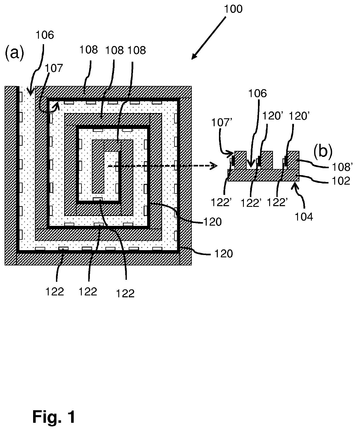
[0028]FIG. 1 schematically shows an embodiment of a lighting assembly 100. The lighting assembly is for emitting high intensity light, for example, more than 500 lumen, or optionally more than 800 lumen, or optionally more than 1200 lumen.

[0029]At the left side of FIG. 1 a top view is presented of the lighting assembly 100. At the right side of FIG. 1 a cross-sectional view of a portion the lighting assembly 100 along a plane defined by the dashed arrow in the top view. The lighting assembly 100 comprises a heat transferring element 102 that comprises upstanding walls 108, 108′. The heat transferring element 102 has a first side 104 and a second side 106 opposite the first side 104. The first side 104 is, in the example of FIG. 1, a heat sink interface to which a heat sink can be thermally coupled. The upstanding walls 108, 108′ extend away from the second side 106 of the heat transferring element 102. The upstanding side walls have wall surfaces 107, 107′ that are adjacent to the s...


PUM

PropertyMeasurementUnit
angleaaaaaaaaaa
angleaaaaaaaaaa
angleaaaaaaaaaa

Abstract

A lighting assembly (100), a light source, a lamp and a luminaire are provided. The lighting assembly comprises a heat transferring element (102) and an elongated structure (120) comprising light emitting elements (122, 122′) and power connections. The heat transferring element comprises at a first side (104) a heat sink interface or a heat sink element. At the second opposite side (106) one or more upstanding walls (108, 108′) are provided extending away from the second side. The upstanding walls are heat conductive and thermally coupled to the first side. The elongated structure is arranged on a wall surface of at least one of the upstanding walls. The wall surface is adjacent to the second side. A surface of the elongated structure through which no light is emitted is thermally coupled to the wall surface. A pattern formed by the elongated structure is a meandering or spiral pattern.

Description

CROSS-REFERENCE TO PRIOR APPLICATIONS[0001]This application is the U.S. National Phase application under 35 U.S.C. § 371 of International Application No. PCT / EP2017 / 064984, filed on Jun. 20, 2017 which claims the benefit of European Patent Application No. 16176566.4, filed on Jun. 28, 2016. These applications are hereby incorporated by reference herein.FIELD OF THE INVENTION[0002]The invention relates to a lighting assembly for emitting high intensity light.[0003]The invention further relates to a light source, a lamp and a luminaire.BACKGROUND OF THE INVENTION[0004]Today Light Emitting Diodes are often used in lighting assemblies or lamps. One Light Emitting Diode (LED) often lacks enough light output to form a lamp that replaces well-known incandescent lamps, halogen lamps or gas discharge lamps even if high lumen Light Emitting Diodes are used. Therefore, in several lighting assemblies, several Light Emitting Diodes are combined into one assembly to increase the total light inten...

Claims


Application Information

Patent Timeline
Patent Type & Authority Patents(United States)
IPC IPC(8): F21V29/76F21V7/00F21V29/56F21S4/10F21S4/24F21V29/15F21Y103/10F21Y103/30F21Y105/18F21Y107/50F21Y107/70F21Y115/10
CPCF21V29/76F21S4/24F21V29/15F21V7/00F21Y2107/70F21Y2103/30F21Y2103/10F21S4/10F21Y2105/18F21V29/56F21Y2115/10F21Y2107/50
Inventor VAN BOMMEL, TIESHIKMET, RIFAT ATA MUSTAFA
Owner SIGNIFY HLDG BV
Learn More