Power control in bidirectional WDM optical link

a power control and optical link technology, applied in electromagnetic transmission, wavelength-division multiplex systems, multi-component communication, etc., can solve problems such as difficult to control cross-talk, difficult to achieve cross-talk control, and difficult to achieve the effect of improving signal-to-noise ratio, improving transmission quality, and controlling cross-talk in both directions

Active Publication Date: 2017-04-25
TELEFON AB LM ERICSSON (PUBL)
View PDF16 Cites 0 Cited by
  • Summary
  • Abstract
  • Description
  • Claims
  • Application Information

AI Technical Summary

Benefits of technology

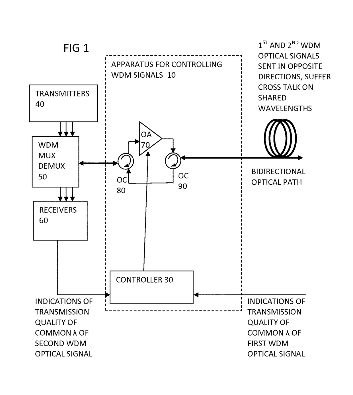
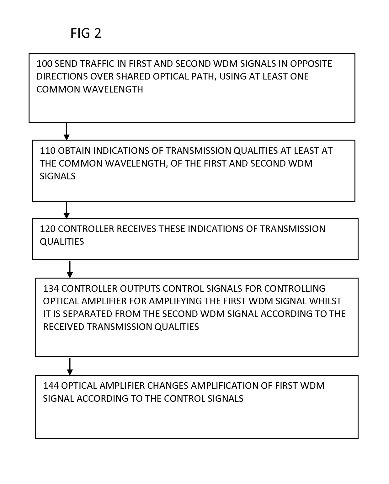
[0009]A benefit of being able to alter relative optical power for the two directions is that the cross talk problem can be improved for example by rebalancing relative amounts of cross talk in the different directions. Thus the capacity benefits of using a common wavelength for both directions can be obtained while using greater optical signal power. This greater optical signal power can mean the optical reach is extended or the numbers of drops can be increased for example. By controlling the WDM signal rather than only controlling the individual wavelengths separately, the number of optical components involved can be limited, the control is simplified and the arrangement is more scalable to larger numbers of wavelengths. By controlling optical power according to the transmission qualities in both directions, the available optical margin in both directions can be used more efficiently, or rebalanced so that the available margin in one direction is taken to improve the optical margin in the other direction for example. The method is applicable to symmetrical links or to non symmetrical links such as optical PONs, and is compatible with other methods such as control of individual wavelengths, or of other optical characteristics such as polarisation or modulation format. See FIGS. 1 and 2 for example as described below.
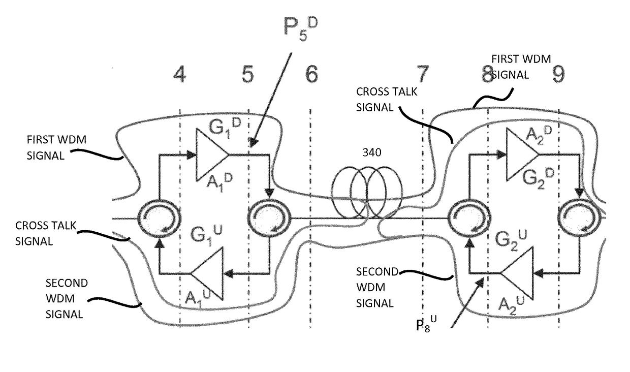
[0010]Any additional features can optionally be added to these features, or can be disclaimed, and some such additional features are described in more detail below. One such additional feature is a step of separating the first and second WDM signals before the optical amplifying step. This can avoid the need to keep the two signals separate up to the amplifying location. Another such additional feature is the optical amplifying step being arranged to occur before the first WDM signal enters the shared optical path. A benefit of controlling optical amplification before the cross talk occurs is that can enable a more direct effect on crosstalk whereas only amplifying afterwards has an indirect effect by helping enable a lower transmission power. By controlling the relative optical powers, the optical power levels can now be optimised for both directions. This amplification of the WDM signal or signals, can enable more efficiency in terms of hardware and more dynamic range than other methods such as tuning output powers of individual wavelength transmitters for example. See FIGS. 1, 3, 12 for example.
[0013]Another such additional feature is a step of determining which direction of transmission of the optical signals has worse transmission quality, and carrying out at least one of the following steps: for that worse direction, increasing the optical power level before the WDM signal enters the shared optical path, and decreasing the optical power level after it leaves the shared optical path, where the cross talk is generated, and for the other direction, decreasing the optical power level before, and increasing the optical power level after, the shared optical path where the cross talk is generated. A benefit is that the signal to noise ratio can be improved in the signal which has worse quality, or the signal to noise ratio can be reduced in the signal which was found to be better quality. In both cases the available optical margin can be shared more equally between the two directions and thus optical reach or other limitation can be optimised. See FIGS. 5, 8, 9 for example.
[0022]Another such additional feature is the optical amplifier being configured to pass the second WDM signal without amplification. A benefit is that cross talk can be controlled with less complexity if one direction is passed. See FIGS. 1, 12 and 14 for example.

Problems solved by technology

For example, cross-talk can arise from bad isolation in optical components or optical reflections.
This makes optical amplification critical.
If, as it actually happens, the isolation of the output optical circulator is not perfect, a significant amount of power generated by the downstream booster amplifier interferes with the upstream signal at the input of the upstream preamplifier, generating cross-talk.
The problem is quite serious considering that, in practical systems, downstream output power is much higher than upstream input power at the pre-amplifier.
So, setting the power levels in order to have the same OSXR in downstream and upstream would result into unbalanced BER performance with downstream BEROLT (measured at the ONT receiver) better than upstream BERONT (measured at the OLT receiver).
This can simplify the control, but reduce the flexibility.

Method used


Image

  • Power control in bidirectional WDM optical link
  • Power control in bidirectional WDM optical link
  • Power control in bidirectional WDM optical link

Examples


Embodiment Construction

[0043]The present invention will be described with respect to particular embodiments and with reference to certain drawings but the invention is not limited thereto but only by the claims. The drawings described are only schematic and are non-limiting. In the drawings, the size of some of the elements may be exaggerated and not drawn to scale for illustrative purposes.

ABBREVIATIONS

AWG Array Waveguide Gratings

BER Bit Error Rate

BIDI-OA Bidirectional Optical Amplifier

EDFA Erbium Doped Fiber Amplifier

Optical Circulator

OLT Optical Line Termination

ONT Optical Network Termination

OSXR Optical Signal to cross-talk Ratio

PON Passive Optical Network

RBS Rayleigh Backscatter

RIN Relative Intensity Noise

RN Remote Node

RX Receiver

TX Transmitter

Xtalk Cross-talk

WDM Wavelength Division Multiplexing

WR Wavelength reuse

DEFINITIONS

[0044]Where the term “comprising” is used in the present description and claims, it does not exclude other elements or steps and should not be interpreted as being restricted to t...


PUM


Abstract

A bidirectional WDM optical communications link has WDM signals sent in opposite directions along a shared optical path and using at least one common wavelength. An optical amplifier (20, 21, 22, 70, A1D, A2U, A2D) optically amplifies (144) a first WDM signal separately from a second WDM signal in the other direction. This separated optical amplification is controlled (134) according to indications of transmission quality at the common wavelength, to alter the relative optical powers of the first and second WDM signals to enable crosstalk at the common wavelength to be limited. Cross talk at the common wavelength can be improved by rebalancing relative amounts of cross talk in the different directions, to enable the capacity benefits of using a common wavelength for both directions to be obtained while using greater optical signal power. This is particularly useful where the optical power is asymmetric, such as in WDM PON systems.

Description

FIELD[0001]The present invention relates to methods of operating a bidirectional WDM optical link, to corresponding apparatus for controlling WDM signals in a bidirectional WDM optical communications link, to bidirectional WDM optical communications links having a shared optical path, and to corresponding computer programs.BACKGROUND[0002]In transport networks, WDM technology particularly DWDM technology offers many benefits in terms of bandwidth capabilities and scalability. Such networks can be passive (PON) or active. WDM-PON brings this benefit most notably in access networks, offering high capacity (currently upgradeable to 10 Gb / s), long distances, no bandwidth contention (virtual point-to-point) and service transparency, together with the possibility of smooth upgrades (per channel) in the protocol and in the bit-rate. WDM-PON is an emerging technology also for mobile backhaul, since broadband services and bandwidth demands are quickly increasing. A conventional WDM-PON is re...

Claims


Application Information

Patent Timeline
Patent Type & Authority Patents(United States)
IPC IPC(8): H04B10/00H04J14/02H04B10/297H04B10/25H04B10/27H04B10/2507
CPCH04B10/2507H04B10/2503H04B10/27H04B10/2972H04J14/02H04J14/0221H04B10/2589
Inventor GIORGI, LUCACAVALIERE, FABIOFALCONI, FABIO
Owner TELEFON AB LM ERICSSON (PUBL)
Why Eureka
Try Eureka