Spark plug

a technology of spark plugs and spark plugs, which is applied in the manufacture of spark plugs, spark plugs, electrical equipment, etc., can solve the problems of difficult to ensure and achieve the effect of improving the joining strength between the noble metal tip and the intermediate member

Active Publication Date: 2019-05-07
NGK SPARK PLUG CO LTD
View PDF7 Cites 0 Cited by
  • Summary
  • Abstract
  • Description
  • Claims
  • Application Information

AI Technical Summary

Benefits of technology

[0022]According to the above structure, since the shortest distance S1 is not less than 0.2 mm, stress applied by moment to the first melt portion at the time of resistance welding can be suppressed. Since the shortest distance S1 is not more than 0.4 mm, a difference in temperature when the noble metal tip and the intermediate member are welded to each other can be suppressed, and thermal stress applied to the first melt portion can be suppressed. Thus, occurrence of cracks in the first melt portion when the intermediate member and the electrode base material are welded to each other can be more effectively suppressed. Therefore, joining strength between the noble metal tip and the intermediate member can be further improved.Application Example 3
[0028]As {(T2−T1)−(S2−S1)} is decreased, local stress applied to the first melt portion can be suppressed. According to the above structure, when {(T2−T1)−(S2−S1)} is not more than 0.4 mm, local stress applied to the second melt portion can be suppressed. Thus, occurrence of cracks in the second melt portion when the intermediate member and the electrode base material are welded to each other can be further suppressed. Therefore, joining strength between the noble metal tip and the intermediate member can be further improved.Application Example 4
[0030]According to the above structure, since temperature is likely to become high due to the vicinity of the center portion of a combustion chamber, joining strength between the noble metal tip and the intermediate member can be improved in the ground electrode required to have joining strength between the noble metal tip and the intermediate member.

Problems solved by technology

Thus, it may be difficult to ensure joining strength between the noble metal tip and the intermediate member.

Method used


Image

  • Spark plug
  • Spark plug
  • Spark plug

Examples


embodiment

A. Embodiment

A-1. Structure of Spark Plug

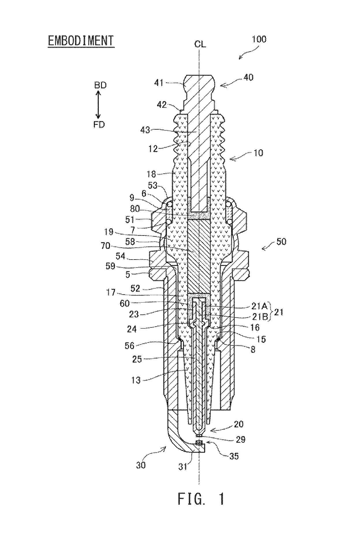
[0037]Hereinafter, a mode of the present invention will be described on the basis of an embodiment. FIG. 1 is a cross-sectional view of a spark plug 100 according to the present embodiment. The alternate long and short dash line shown in FIG. 1 represents an axial line CL of the spark plug 100. The direction parallel to the axial line CL (the up-down direction in FIG. 1) is also referred to as the axial direction. The radial direction of a circle located on a plane perpendicular to the axial line CL and centered on the axial line CL is also referred to merely as “radial direction”, and the circumferential direction of the circle is referred to merely as “circumferential direction”. The downward direction in FIG. 1 is also referred to as a front end direction FD, and the upward direction is also referred to as a rear end direction BD. The lower side in FIG. 1 is referred to as the front side of the spark plug 100, and the upper side in FIG. 1 ...


PUM


Abstract

An electrode of the spark plug includes a first melt portion formed between a body portion of an intermediate member and a noble metal tip; and a second melt portion that is formed, between a flange portion of the intermediate member and an electrode base material, at least at a position of intersection with an axial line of the noble metal tip. In a cross section including the axial line of the noble metal tip, when: a diameter of the noble metal tip is denoted by Tw; the shortest distance between the second melt portion and a boundary between the first melt portion and the intermediate member is denoted by S1; and the longest distance between the second melt portion and the boundary between the first melt portion and the intermediate member is denoted by S2, 1.0 mm≤Tw≤1.2 mm and (S2−S1)≤0.3 mm are met.

Description

RELATED APPLICATIONS[0001]This application is a National Stage of International Application No. PCT / JP16 / 04540 filed Oct. 11, 2016, which claims the benefit of Japanese Patent Application No. 2015-218981, filed Nov. 6, 2015, the entire contents of which are incorporated herein by reference.FIELD OF THE INVENTION[0002]The present invention relates to a spark plug for igniting combustion gas in an internal combustion engine.BACKGROUND OF THE INVENTION[0003]In a spark plug for igniting combustion gas in an internal combustion engine, a gap for discharging a spark is formed between a center electrode and a ground electrode. Here, a spark plug is known in which a noble metal tip is mounted, via an intermediate member, to an electrode base material of the ground electrode (e.g., Japanese Patent Application Laid-Open (kokai) No. 2013-33670). The intermediate member is used for reducing a possibility of occurrence of a trouble when a noble metal tip is directly mounted on an electrode base ...

Claims


Application Information

Patent Timeline
Patent Type & Authority Patents(United States)
IPC IPC(8): H01T13/20H01T13/38H01T13/39H01T13/34H01T13/32
CPCH01T13/39H01T13/20H01T13/38H01T13/34H01T13/32H01T21/02H01T1/22
Inventor IGARASHI, TOMOYUKI
Owner NGK SPARK PLUG CO LTD
Why Eureka
Try Eureka