Wavelength conversion device, and light source system and projection system therefor

a conversion device and wavelength technology, applied in the field of illumination and display technologies, can solve the problems of inconvenient use of metal substrates, poor conductivity of silica gel overall, and inconvenient use of projection devices, so as to reduce material use, reduce cost, and high quality color wheels

Active Publication Date: 2019-05-14
APPOTRONICS CORP LTD
View PDF24 Cites 4 Cited by
  • Summary
  • Abstract
  • Description
  • Claims
  • Application Information

AI Technical Summary

Benefits of technology

[0005]The main technical problem solved by embodiments of the present invention is to provide a wavelength conversion device that can withstand high temperature and can maintain its structural stability, as well as related light source system and projection system.

Problems solved by technology

Because the thermal conductivity of silica gel is relatively poor, and it tends to become darkened in a high temperature environment, the overall device is not suitable for working with high power excitation light.
The sintering temperature for glass powder is relatively high, often above 500 degrees C., so it is not suitable for metal substrates, in particular aluminum substrate, because the highly thermally conductive and thin metal plate may experience problems of softening, deformation, oxidization, high thermal expansion, etc.
It also makes it difficult for the sintered phosphor layer to adhere to the substrate.
1. Ceramic carriers are used to replace conventional mirror-surface metal plates. Because ceramic materials have higher melting temperatures than those of metals, they can withstand higher temperatures than metals. Also, the thermal resistance of the interface between the ceramic carrier and the phosphor materials is relatively low, so the heat generated by the phosphor materials can be conducted to the ceramic carrier and dissipated to the environment. This improves the thermal stability of the wavelength conversion device. Moreover, the thermal expansion coefficients of ceramics are relatively low, so they resist deformation even at high temperatures. Further, the thermal expansion coefficients of ceramics and the phosphor layer are close to each other, so even if there is a small amount of deformation, it does not affect the ability of the phosphor layer to adhere to the ceramic substrate.
2. Because ceramic materials have relatively low toughness and relatively high brittleness, for a wavelength conversion device where the carrier substrate for the phosphor materials is an integral ceramic piece, when it is illuminated by high intensity excitation light, the degrees of thermal expansion in inner and outer regions are large. Such non-uniform expansion can cause the ceramic to crack, which in turn can cause the color wheel to burst or break, and the color wheel will completely cease to function. In embodiments of the present invention, the ceramic carriers are divided into multiple pieces, which are then adhered to a support structure made of a metal, a metal alloy, or a composite material of metal and inorganic materials. Compared to the design of forming different phosphor materials on the same integral ceramic carrier, the chances of crack, break or burst are greatly reduced.
On the same ceramic substrate, it is difficult to coat different phosphor layers in one pass using blade-coating, so different color phosphors need to be coated and sintered separately in multiple passes, making the production cycle long.
Also, different color phosphor layers can be sintered separately and concurrently, which shortens the production cycle.
Using a large sized integral ceramic piece, when special processing is required, such as surface polishing, metal brazing, surface coating, etc., the larger the carrier size, the higher the processing difficulty.
); thus, when designing high performance color wheel with complex structures, the processing parameters have to be chosen by compromise due to these limitations, making it hard to achieve optimum result for each phosphor material and each processing technique.

Method used


Image

  • Wavelength conversion device, and light source system and projection system therefor
  • Wavelength conversion device, and light source system and projection system therefor
  • Wavelength conversion device, and light source system and projection system therefor

Examples


first embodiment

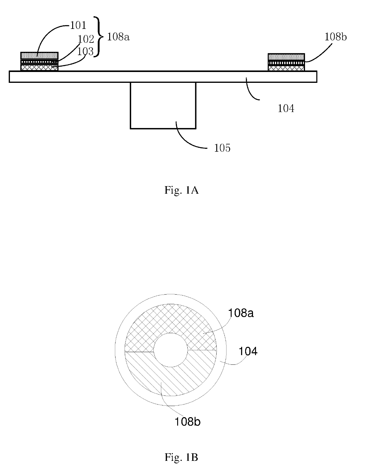
[0051]Referring to FIGS. 1A and 1B, in this embodiment, the wavelength conversion device includes a support structure 104 and two wavelength conversion modules 108a and 108b. Each wavelength conversion module includes a ceramic carrier 103, and a phosphor layer 101 and a reflective layer 102 disposed on the ceramic carrier 103.

[0052]As shown in FIGS. 1A and 1B, the support structure 104 is a round base plate, preferably formed of a metal, a metal alloy, or a composite material of metal and inorganic materials. The metal may be aluminum, copper, silver, etc. The metal alloy may be brass, aluminum alloy, copper aluminum alloy, etc. The composite material of metal and inorganic material is a composite of metal and inorganic material, such as diamond-copper, boron nitride-copper, etc. The support structure has a ring shaped region which is centered on the center of the round base plate.

[0053]There are two ceramic carriers 103, respectively shaped like a half of a ring; they are arranged...

second embodiment

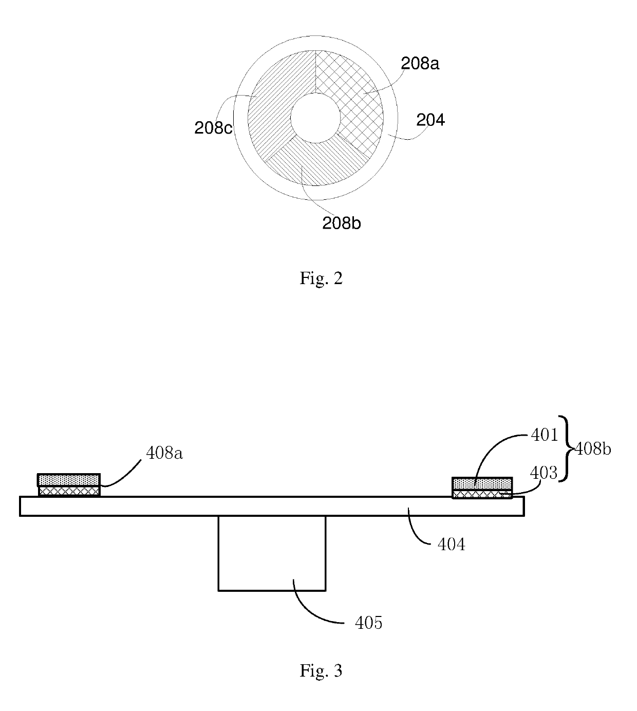
[0065]As shown in FIG. 2, in this embodiment, the support structure 204, drive mechanism, ceramic carriers, adhesives, reflective layers and phosphor layers are similar to those in the first embodiment and detail descriptions are omitted here.

[0066]A difference between this embodiment and the first embodiment is that, there are three wavelength conversion modules 208a, 208b and 208c, each having an arc shape; they are arranged on and adhered to a ring shaped region of the support structure 204 to form a ring shape. Moreover, the phosphor material in the phosphor layer on each ceramic carrier is a monochromatic phosphor that is excited to emit a converted light of one color, and different colored phosphor materials are provided on different ceramic carriers.

[0067]For example, as shown in FIG. 2, the phosphor materials on the three wavelength conversion modules 208a, 208b and 208c are respectively red phosphor, yellow phosphor and orange phosphor. The sequence of the three phosphors c...

third embodiment

[0072]In this embodiment, except for the reflective layer, the other components are similar to those of the first and second embodiments, and detailed descriptions are omitted here.

[0073]A difference between this embodiment and the first and second embodiments is that for the reflective layer, a diffuse reflection layer replaces the total reflection film.

[0074]The diffuse reflection layer is located between the phosphor layer and the ceramic carrier, and includes white scattering particles, which function to scatter the incident light. The white scattering particles are typically a powder of a salt or an oxide, and the particle size ranges from 50 nanometers to 5 microns. Examples include aluminum oxide, titanium oxide, aluminum nitride, magnesium oxide, boron nitride, zinc oxide, zirconium oxide, barium sulfate, etc. which are ultra-white single powder particles, or a mixture of two or more of the above powder particles. These white scattering material absorbs virtually no light, a...


PUM

PropertyMeasurementUnit
particle sizeaaaaaaaaaa
particle size distributionaaaaaaaaaa
reflectivityaaaaaaaaaa

Abstract

Disclosed are a wavelength conversion device, and a light source system and a projection system therefor. The wavelength conversion device comprises a supporting structure and a plurality of wavelength conversion modules arranged together, each wavelength conversion module comprising a ceramic carrier and a phosphor material provided thereon. The supporting structure ensures that the plurality of wavelength conversion modules remain fixed relative to one another. The light source system and the projection system both comprise the present wavelength conversion device. The use of ceramic material as the carrier for the phosphor material enables high temperature resistance, and prevents detachment of the phosphor material due to deformation at high temperatures. In addition, such a modular wavelength conversion device does not crack easily, and has a flexible design and shorter production cycle.

Description

BACKGROUND OF THE INVENTIONField of the Invention[0001]This invention relates to illumination and display technologies, and in particular, it relates to a wavelength conversion device, and related light source system and projection system.Description of Related Art[0002]Wavelength conversion methods which use solid state light sources such as laser diodes (LD) or light emitting diodes (LED) to generate an excitation light to excite wavelength conversion materials such as phosphors can generate high brightness light having wavelengths different from those of the excitation light. Such light generation techniques have the advantages of high efficiency and low cost, and have become a dominating technology for providing white light and monochromatic lights. The light source according to this technology includes an excitation light source and a wavelength conversion device, where the wavelength conversion device includes a reflective substrate and a phosphor material layer coated on the ...

Claims


Application Information

Patent Timeline
Patent Type & Authority Patents(United States)
IPC IPC(8): G03B21/20G02B17/00G03B33/08C09K11/77G02B26/00H04N9/31F21V9/30F21V9/40
CPCG02B26/008C09K11/7774F21V9/30G03B21/204G03B21/2066G03B33/08G02B17/006H04N9/3158F21V9/45F21V7/30F21V13/08F21V9/38F21V9/32F21V9/08
Inventor LI, QIANXU, YANZHENG
Owner APPOTRONICS CORP LTD
Why Eureka
Try Eureka