Belt drive system

a belt drive and belt drive technology, applied in the direction of clutches, agriculture tools and machines, gears, etc., can solve the problems of premature failure of the supporting bearings, false brinelling of the concerned elements, and the statically loaded bearings of the driven pulley and/or the driven sha

Active Publication Date: 2019-05-21
AGCO CORP
View PDF52 Cites 2 Cited by
  • Summary
  • Abstract
  • Description
  • Claims
  • Application Information

AI Technical Summary

Benefits of technology

[0011]As the pulley is provided on the fixed housing, the pulley will rotate relative to the housing regardless of the engagement status of the pulley with the shaft. Accordingly, the interface between the pulley and the housing experiences dynamic loading for all rotating conditions of the pulley—the bearings supporting each pulley continue to turn when selectively engaged with the shaft. This prevents damage or failure at the interface due to static loading of the interface of the pulley, e.g. due to false brinelling, leading to improved bearing longevity.
[0070]The use of a separate plate which can be coupled to the second pulley allows for ease of assembly of the system, allowing for components of the system to be built up in stages from one side of the system.

Problems solved by technology

A problem with such prior art systems is that when a driven pulley is engaged to rotate the driven shaft, the bearings which support the driven pulley and / or driven shaft are statically loaded when supporting the maximum loads induced by the drive belt.
This then causes the rolling elements (e.g. balls, rollers, etc.) within the bearings to undergo repeated loading while stationary, which can lead to false brinelling of the concerned elements.
Such false brinelling of bearing systems can result in premature failure of the supporting bearings, requiring costly service and repair of the belt drive system.

Method used


Image

  • Belt drive system
  • Belt drive system
  • Belt drive system

Examples


Embodiment Construction

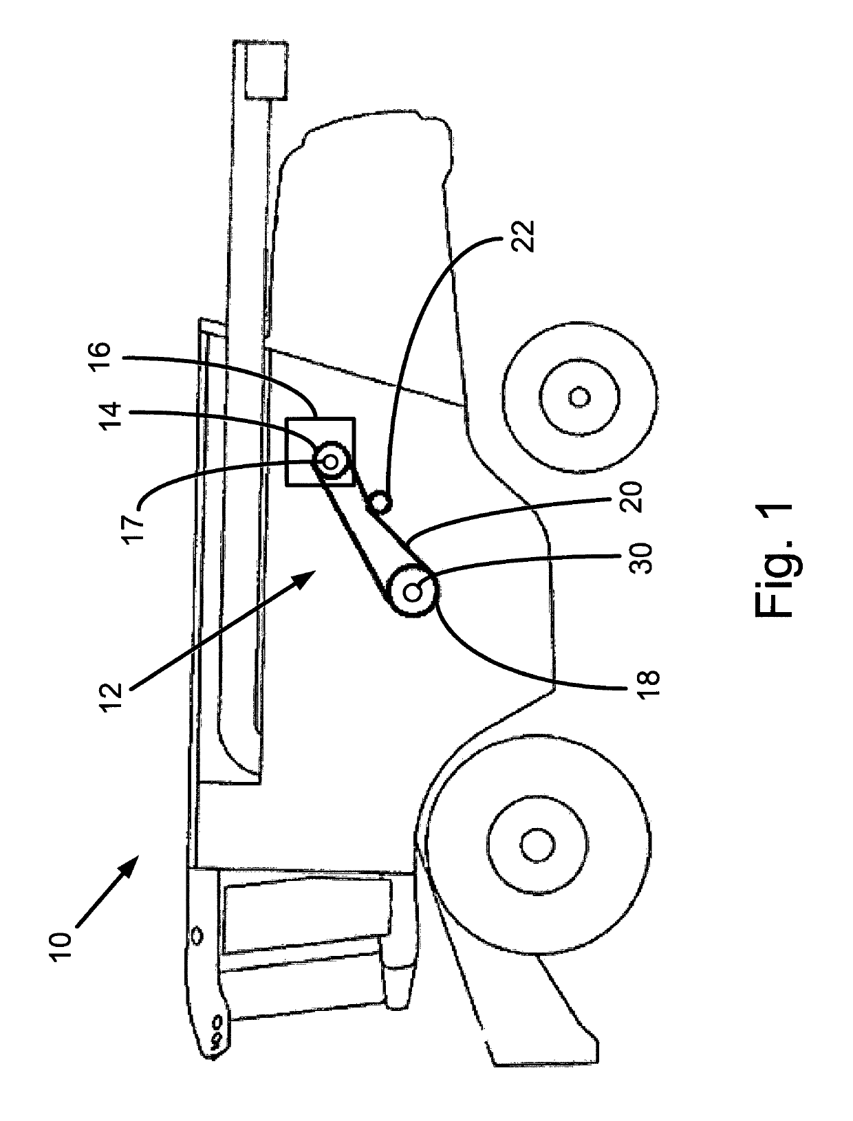
[0077]FIG. 1 shows an agricultural vehicle in the form of a combine harvester 10. The harvester 10 is provided with a belt drive system 12 for use in a material handling system of the harvester 10. The belt drive system 12 comprises a driver pulley 14 which is rotated by a connected drive system 16. The drive system 16 rotates an input driver shaft 17, to which the driver pulley 14 is mounted. The driver pulley 14 is coupled with a driven pulley 18 via an endless belt 20 which is provided around the pulleys 14,18. A belt tensioner 22 is provided in contact with the belt 20 to ensure the belt 20 is maintained in position on the pulleys 14,18 during use. The driven pulley 18 is rotated under action of the driver pulley 14, and is used to provide rotation to suitable components of the harvester 10. For example, the driven pulley 18 may be coupled with a rotary chopper, a conveyor, an auger, an impeller, a rotary drum, etc. The belt drive system 12 may comprise a single set of belt-coup...


PUM


Abstract

A belt drive system for a vehicle, such as a combine harvester. The belt drive system uses a driven pulley which is selectively engageable with a driven shaft to supply rotation to the shaft. The pulley is mounted on a fixed, i.e. non-rotating, housing using suitable bearings, such that the bearings of the pulley continue to rotate and are dynamically loaded for all rotation conditions of the driven pulley, i.e. whether the pulley is engaged with the shaft or not. This prevents damage to the bearings due to false brinelling.

Description

BACKGROUND OF THE INVENTIONField of the Invention[0001]The present invention relates to a belt drive system for a vehicle, in particular a selectable belt drive system for an agricultural vehicle such as a harvester.Description of Related Art[0002]Belt drive systems are often used in vehicles such as combine harvesters to provide rotating motion to vehicle components. Such systems generally comprise a rotating driver pulley connected to a driven pulley via a belt. The driven pulley may be connected to the component to be rotated via a shaft or similar element.[0003]It is common for combine harvesters to include driven systems which require a change in operating speed for improved material handling, performance, or efficiency. Many manufacturers have implemented two-speed belt drives to meet this requirement as an economical alternative to multi-ratio gearboxes. These drives are comprised of two driver and driven pulleys with either end, driver or driven, fixed upon a shaft and the o...

Claims


Application Information

Patent Timeline
Patent Type & Authority Patents(United States)
IPC IPC(8): F16H7/02F16D11/14F16H7/12F16D21/04A01D69/06F16H9/04
CPCF16H9/04A01D69/06F16D21/04F16H7/02F16D11/14F16H7/12
Inventor WILLIAMS, NICHOLAS H.VEER, ANDREW MARK
Owner AGCO CORP
Why Eureka
Try Eureka