Method for improving the steering feel in the case of a recirculating ball steering system

Active Publication Date: 2019-06-04
KNORR-BREMSE SYST FUER NUTZFAHRZEUGE GMBH
View PDF7 Cites 0 Cited by
  • Summary
  • Abstract
  • Description
  • Claims
  • Application Information

AI Technical Summary

Benefits of technology

The invention is a method to improve the steering feel in a recirculating ball steering system by reducing the stick-slip effect. This method involves opening valves to decrease the pressure in the working chamber of the steering piston when it is approaching a stop or stop after a steering movement. This decreases the friction between the components, resulting in a more pleasant steering feel. This method can also be used in combination with a motor to further compensate for the stick-slip effect. The steering angle speed signal is processed to identify the direction of movement and the pressure in the working chamber is adjusted accordingly to prevent excessive movement of the steering piston. Overall, this method improves the steering feel of recirculating ball steering systems while still being cost-efficient.

Problems solved by technology

It turned out that known recirculating ball steering systems have an unwanted so-called stick-slip effect, which has a negative impact on the steering feel.
Furthermore, there is an associated increased wear.

Method used


Image

  • Method for improving the steering feel in the case of a recirculating ball steering system
  • Method for improving the steering feel in the case of a recirculating ball steering system
  • Method for improving the steering feel in the case of a recirculating ball steering system

Examples


Embodiment Construction

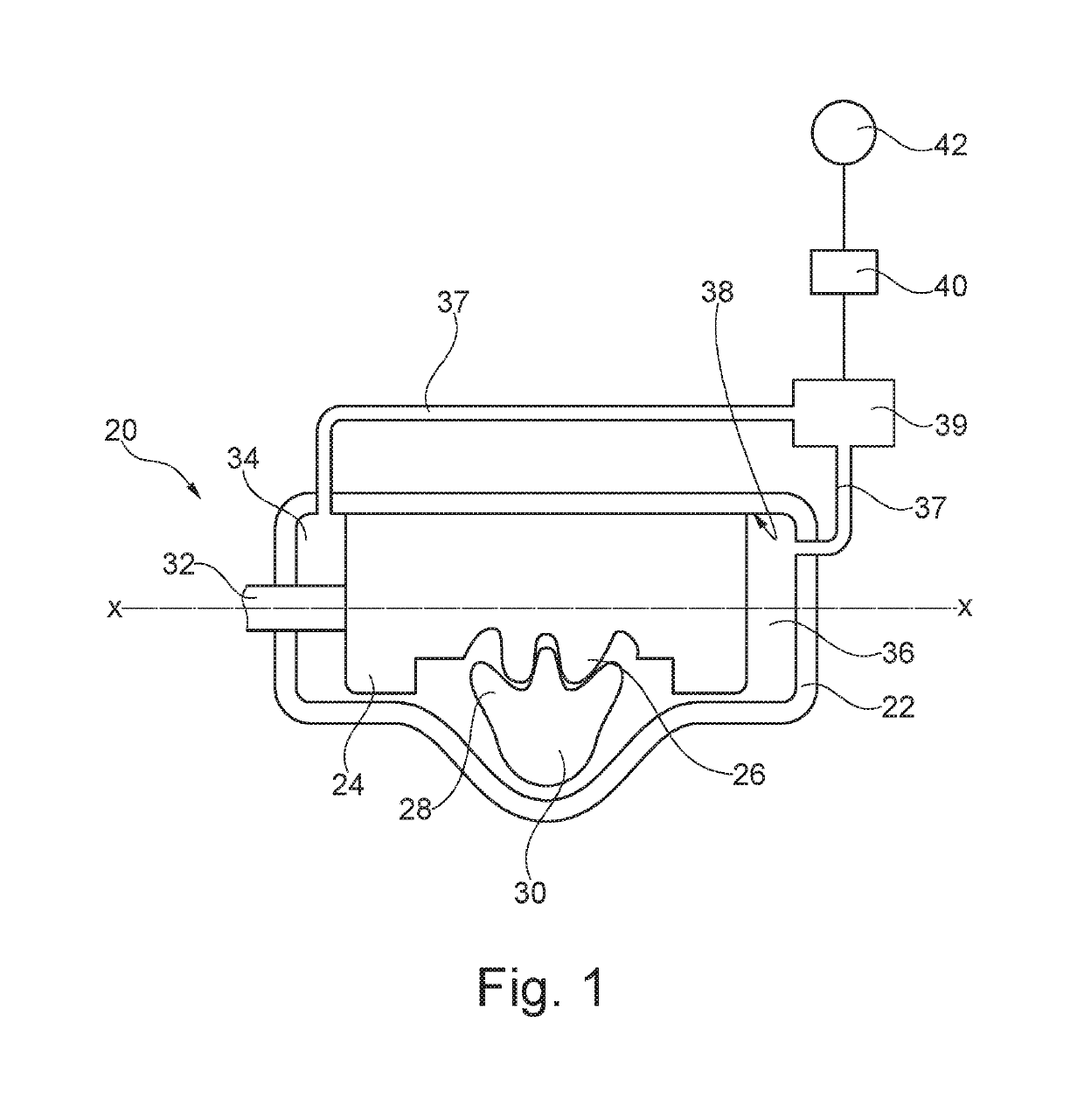
[0028]A recirculating ball steering system 20 according to the invention is shown in cross section in FIG. 1 in a highly simplified illustration. This schematic diagram is to only be understood in an exemplary manner, the invention is in no way to be limited to the shown figures. To be able to better illustrate the invention, the figures do not represent the components true to scale. In addition to a variety of non-illustrated components, it has a steering housing 22, in which a steering piston 24 can be moved along a longitudinal axis X-X.

[0029]A circulating ball steering system 20 according to the invention is shown in a highly simplified illustration in cross section in FIG. 1. In addition to a variety of non-illustrated components, it has a steering housing 22, in which a steering piston 24 can be moved along a longitudinal axis X-X.

[0030]The steering piston 24 has a tooting area 26, with which teeth 28 of a segment shaft 30 engage. A longitudinal movement of the steering piston...


PUM


Abstract

The invention relates to a method for compensating a stick-slip effect in the case of a recirculating ball steering system (20) having a steering housing (22), in which a steering piston (24) is supported between a first working chamber (34) and a second working chamber (36), wherein the steering piston (24) has a toothed region (26) on the steering-piston outer wall of the steering position, with which toothed region teeth (28) of a segment shaft (30) mesh, the steering piston (24) can be moved along a longitudinal axis X-X, the working chambers (34, 36) are connected to a control valve (39) by means of pressure-medium lines in order to provide steering assistance, the control valve (39) is connected to a processor unit (40), by means of which valves of the control valve (39) can be actuated, and the processor unit (40) is connected to a sensor (42), which determines rotation of the steering column both in a first direction of rotation and in a second, opposite direction of rotation. When a rotational motion of the steering column in a first direction occurs and thereafter the rotational motion in said direction nearly or completely stops, the valves of the control valve (39) are opened by the processor unit (40) in such a way that the pressure in the working chamber (34, 36) of the steering piston (24) facing away from the direction of motion of the steering piston (24) is reduced and immediately thereafter the pressure in the same working chamber (34, 36) is increased again.

Description

RELATED APPLICATIONS[0001]This application is a National Phase of PCT Patent Application No. PCT / EP2015 / 078953 having International filing date of Dec. 8, 2015, which claims the benefit of priority of German Patent Application No. 10 2014 118 567.6 filed on Dec. 12, 2014. The contents of the above applications are all incorporated by reference as if fully set forth herein in their entirety.FIELD AND BACKGROUND OF THE INVENTION[0002]The invention at hand shows a method for improving the steering feel of a recirculating ball steering system, in particular for compensating a stick-slip effect.SUMMARY OF THE INVENTION[0003]In the case of a recirculating ball steering system, a steering piston is supported be abstract tween a first working chamber and a second working chamber in a steering housing, wherein the steering piston has a toothed region on its steering piston outer wall, with which teeth of a segment shaft engage. To provide steering assistance, the working chambers are connect...

Claims


Application Information

Patent Timeline
IPC IPC(8): B62D5/12B62D5/24B62D5/04B62D5/083B62D7/15
CPCB62D5/24B62D5/0463B62D5/12B62D5/0835B62D7/159
Inventor MULLER, JENS-HAUKESCHULTE, OLAFKIRSCHBAUM, SVEN
Owner KNORR-BREMSE SYST FUER NUTZFAHRZEUGE GMBH
Why Eureka
Try Eureka