Self-matching phase shifter/attenuator

a phase shifter and self-matching technology, applied in the field of variable phase shifters and attenuators, can solve the problem of low return loss, and achieve the effect of reducing the return loss and broadening the range of phase shifts

Active Publication Date: 2019-06-04
PSEMI CORP
View PDF6 Cites 0 Cited by
  • Summary
  • Abstract
  • Description
  • Claims
  • Application Information

AI Technical Summary

Benefits of technology

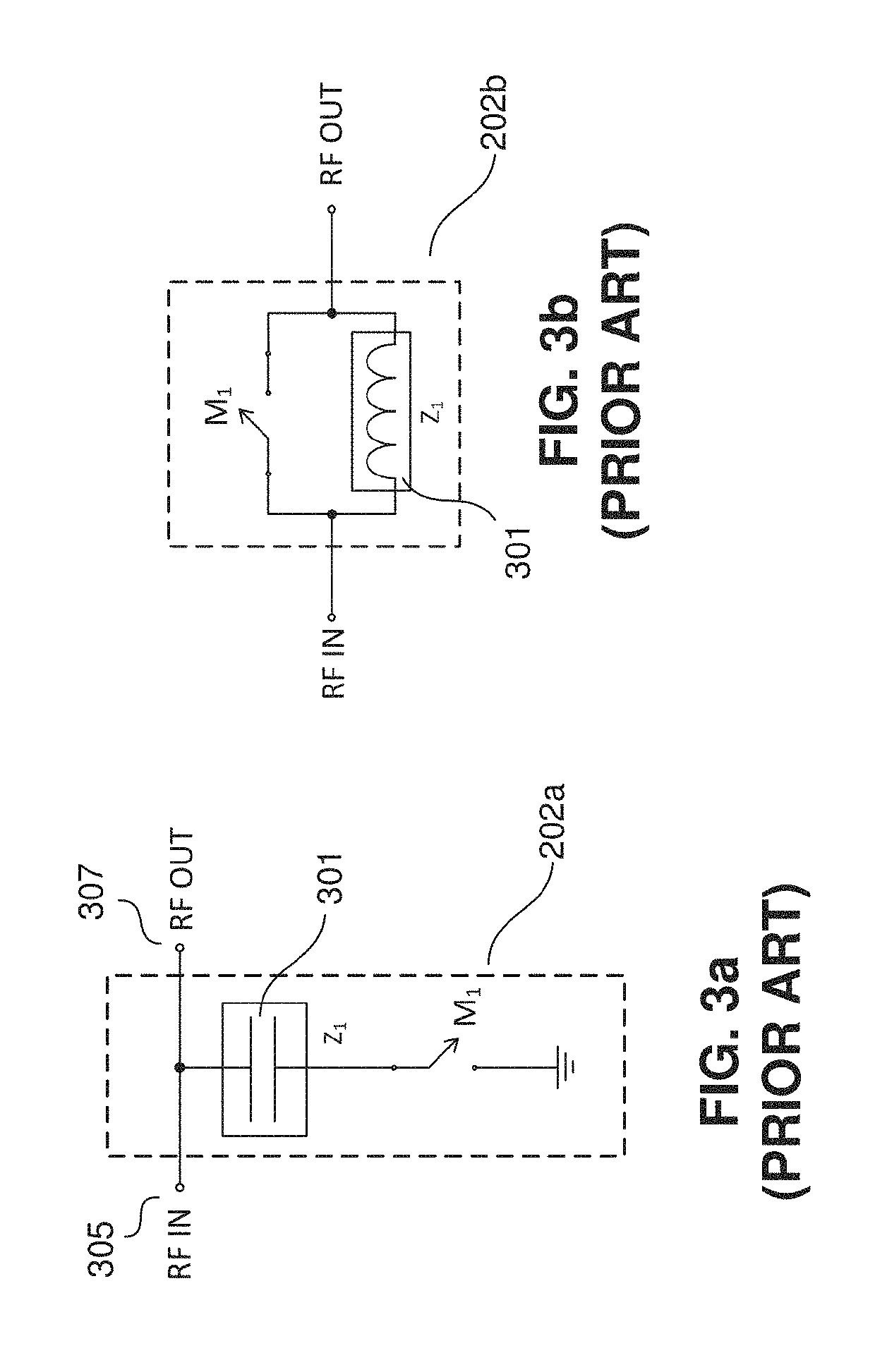
[0011]In the phase shifter, the series reactive component is coupled in series with the signal path. A bypass switch operates in coordination with the ground switch. In a first embodiment, the closing of ground switches is alternated with the opening of bypass switches. By ensuring that the number of ground switches that are closed is no greater than one more than the number of bypass switches that are open, the impedance at the input and output of the self-matching variable phase shifter self corrects the impedance as additional phase shift steps are implemented. In a second embodiment, whenever a ground switch is closed, an associated bypass switch is opened. In either embodiment, any number of incremental impedance matched phase shifter elements can be coupled in series to form a self-matching variable phase shifter having a broad range of phase shifts selectable in relatively small discrete steps. In other embodiments, larger phase shift steps can be used, assuming the increase in return loss introduced by each element that results from using larger phase shift steps is tolerable. Using smaller steps allows the amount of phase shift to be changed while maintaining a relatively constant input and output impedance, resulting in lower return loss.

Problems solved by technology

Using smaller steps allows the amount of phase shift to be changed while maintaining a relatively constant input and output impedance, resulting in lower return loss.

Method used


Image

  • Self-matching phase shifter/attenuator
  • Self-matching phase shifter/attenuator
  • Self-matching phase shifter/attenuator

Examples


Embodiment Construction

[0036]FIG. 5 is an illustration of a self-matching phase shifter 500 in accordance with one embodiment of the disclosed method and apparatus. In some embodiments, the self-matching phase shifter 500 comprises several impedance matched incremental phase shifter elements 502 (i.e., n such elements 502). Each of the n elements 502 comprise an input port 504, an output port 506, a shunt reactive component, such as a capacitor 508, a series reactive component, such as an inductor 512, a ground switch 510 and an associated bypass switch 514.

[0037]Each of the switches 510, 514 is controlled by a switch control line 516, 518. In some embodiments, a phase shift control interface 520 has control signal output ports that output signals to control the switches 510, 514. An input 522 to the phase shift control interface 520 indicates the desired amount of phase shift. In some such embodiments, the phase shift control interface 520 closes one switch for each discrete phase shift step. The amount ...


PUM


Abstract

A self-matching phase shifter / attenuator including several incremental impedance matched phase shifter / attenuator elements is disclosed. Each incremental impedance matched phase shifter element comprises a reactive component (such as either a capacitor or inductor) that can be coupled in shunt to the signal path. The shunt reactive component is coupled in series with a ground switch. When closed, the ground switch connects the shunt reactive component to ground. When the ground switch is open, the switch removes the shunt reactive component from the circuit. In addition, each incremental impedance matched phase shifter element comprises a series reactive component having a reactance that is typically equal and inverse of that of the shunt reactive component.

Description

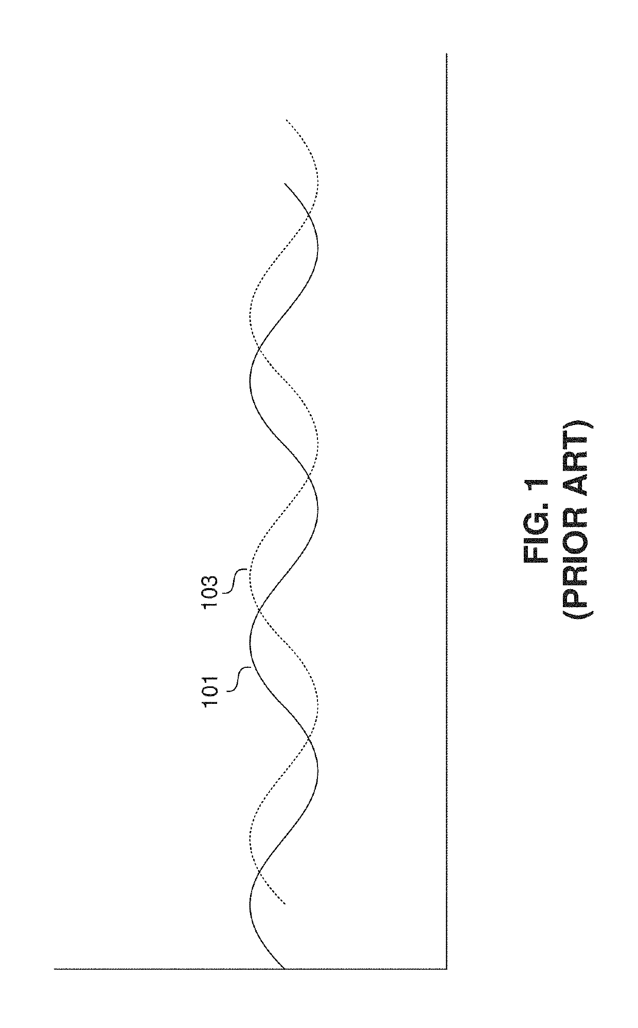
BACKGROUND[0001](1) Technical Field[0002]Various embodiments described herein relate to phase shifters and attenuators and more particularly to variable phase shifters and attenuators having self-matching impedance.[0003](2) Background[0004]From time to time, it is desirable to be able to variably alter the phase of an electrical signal within an electrical circuit. A phase shift is a movement along the time axis of a signal in which voltage or current is plotted against time. FIG. 1 shows a solid line 101 representing three periods of a first sine wave plotted with voltage in the vertical axis and time in the horizontal axis. A dotted line 103 represents three periods of a second sine wave shifted by 90 degrees with respect to the first sine wave 101. It can be seen that the second sine wave 103 is a perfect replica of the first sine wave 101 with the exception of the phase shift (i.e., the sliding along the time axis). Accordingly, it can be said that the sine wave 101 was shifted...

Claims


Application Information

Patent Timeline
Patent Type & Authority Patents(United States)
IPC IPC(8): H03K5/13H03H7/25H03H7/20H03H11/24H03H11/28H03H11/20H03H7/38
CPCH03H11/20H03H7/20H03H11/245H03H11/28H03H7/25H03H7/38
Inventor SHRIVASTAVA, RAVINDRANATH
Owner PSEMI CORP
Why Eureka
Try Eureka