
Endotracheal intubation and supraglottic airway device

a supraglottic airway and endotracheal technology, applied in the field of medical airway management devices, can solve the problem that visualization during intubation is not mandatory, and achieve the effect of easy and gentle endotracheal intubation and inexpensive manufacturing

Inactive Publication Date: 2019-06-11
SUN YANG
View PDF39 Cites 2 Cited by
  • Summary
  • Abstract
  • Description
  • Claims
  • Application Information

AI Technical Summary

Benefits of technology

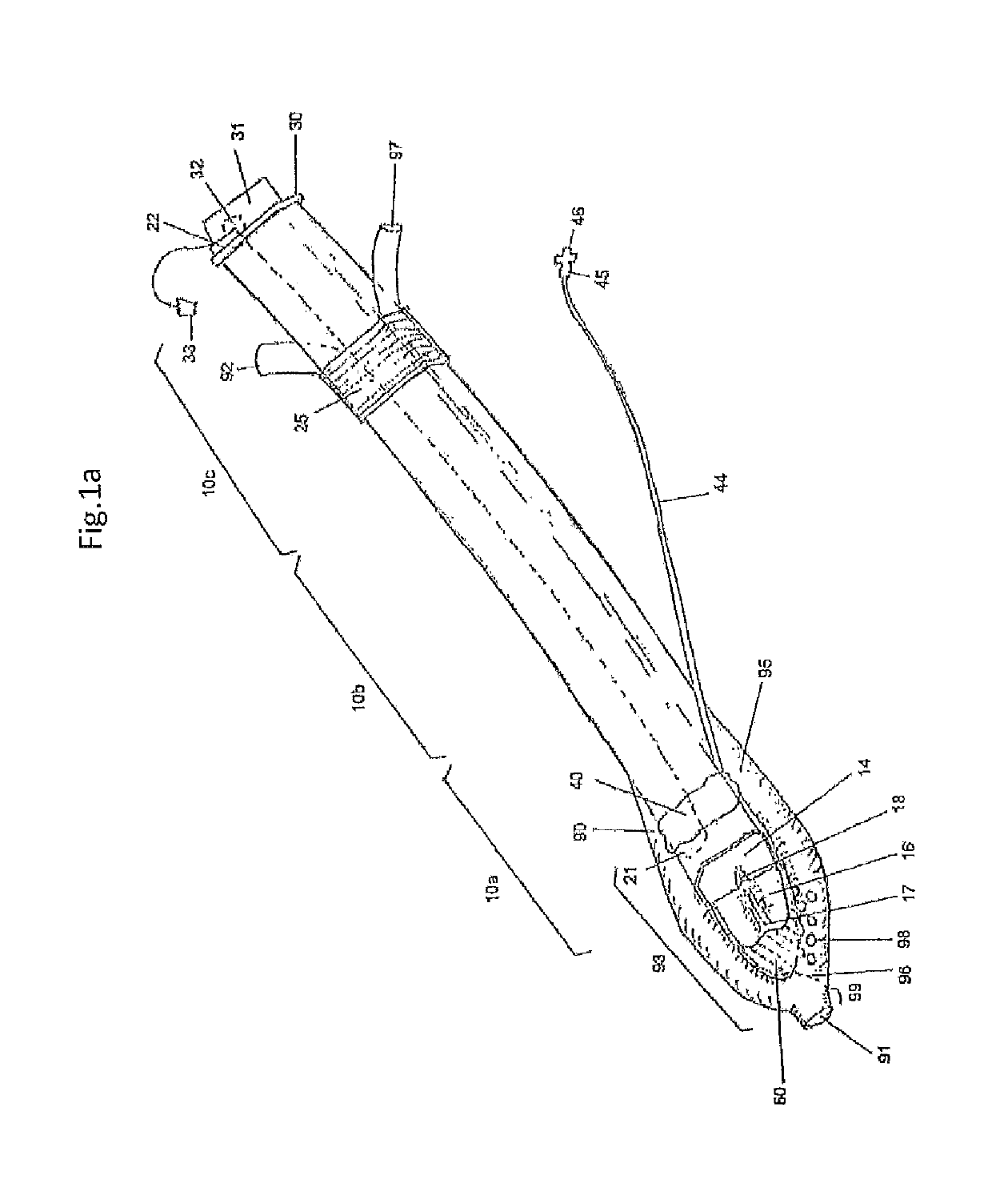
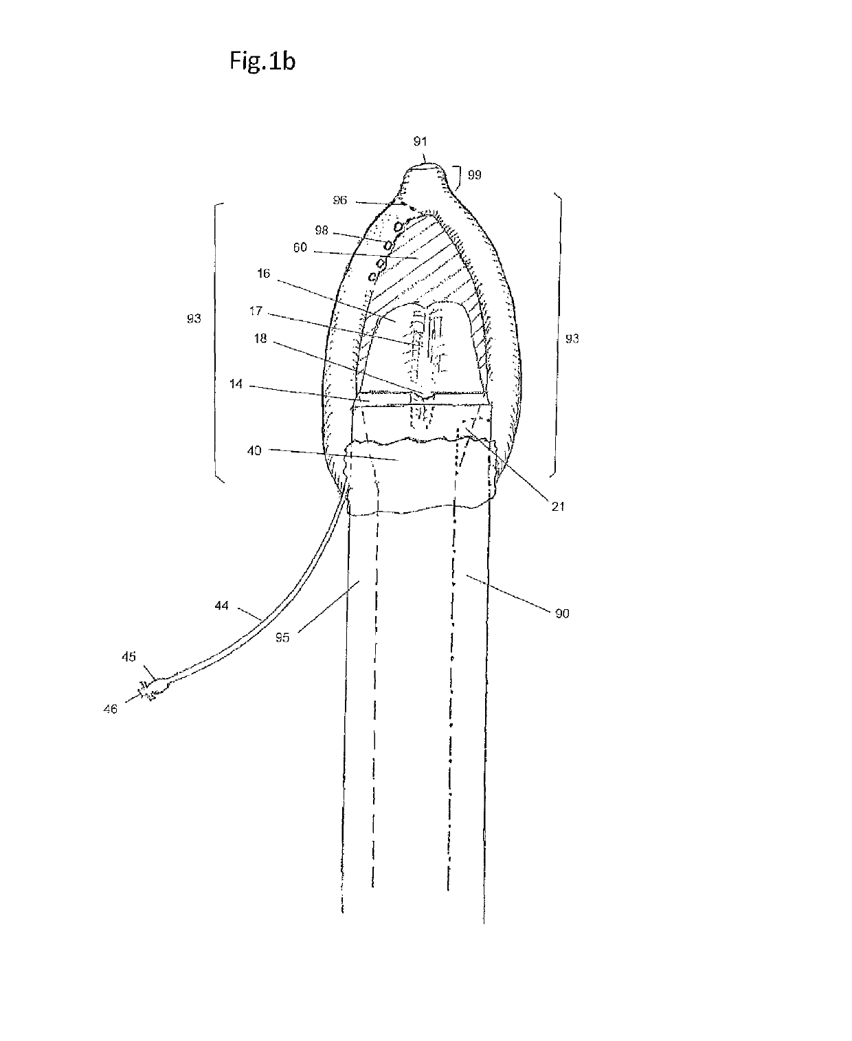
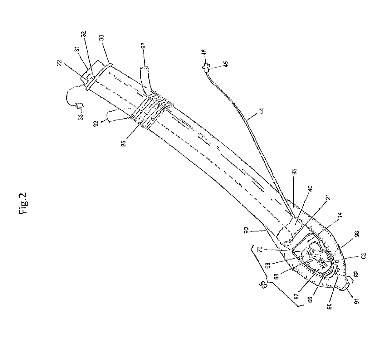
[0037]The present invention is an intubation and supraglottic airway device, brief as ISAD, with various invention embodiments to provide easy and gentle endotracheal intubation, with a choice of “blind intubation”. “Blind intubation” means during an intubation an operator does not have to visualize the laryngeal inlet or vocal cord structure directly or indirectly to accomplish the intubation. At present invention operator also can choose to perform the intubation under visualization of a fiber optics scope. The ISAD also can be used as a supraglottic airway device for spontaneous ventilation and positive pressure mechanical ventilation. Further, the ISAD can provide an alternative access for respiratory treatment and laryngology for inspection, removing a foreign body, biopsy and some oral dental surgeries. The present invention can be widely used in multiple medical specialties without waiting a sub-specialty trained physician in emergency difficulty airway cases and be used as an alternative tool for positive pressure mechanical ventilations without an endotracheal tube. And the present invention can also provide an esophageal gastric access for a fiber optic scope probe passing through for diagnosis and treatment procedure of gastric intestinal diseases. Finally, it is also an objective of this invention to be inexpensive to manufacture.
[0038]The device may be constructed from any suitable plastics or polymers, or other suitable materials with certain flexibility that allows insertion into a patient's throat without damaging throat tissues.
[0041]In a preferred embodiment, top wall of the air tube distal segment is configured to have an epiglottis lifting and holding plate, brief as ELHP. The ELHP obliquely rests inside the lumen of the tube system distal segment. Its tip could be curved and extend outside the lumen of the air tube distal end. The ELHP is designed to be lifted by an incoming stylet or an endotracheal tube. The ELHP can be hold in the elevated position by one or two pairs of lateral support means and consequently the ELHP can keep the epiglottis being elevated position for ventilation, especially for positive pressure mechanical ventilation.
[0043]An inflatable balloon is configured to wrap around the a length of the tube system distal segment configured to push up the tube system distal segment and ATAP for an alignment control process, and to push the surrounding tissues away to expose the laryngeal inlet when the device is in an engagement position or near the engagement position and an inflatable balloon is inflated thorough an inflation tube. At same time the inflatable balloon forms a seal with surrounding tissue to prevent air leakage. The inflated balloon can also hold the air tube distal end opening in front of the laryngeal inlet.
[0045]At the distal end esophageal blocker has an opening which is continuation of the distal orifice of the first drainage tube to drain fluid or small particles from upper esophagus. The second drainage tube distal end is closed and attaches to the side wall of distal end of the first drainage tube to form the drainage loop. At distal portion of the convex segment of the second drainage tube, the multiple penetrating holes in the wall are configured to drain the fluid or secretions accumulated in the subglottic area and vent out the escaped air to prevent the stomach insufflation when positive pressure in ventilation is excessively high.
[0047]And also the close contact between the restraint plate and the ATAP can help to provide a barrier to prevent regurgitated fluid accumulated in subglottic area getting into the laryngeal inlet.

Problems solved by technology

However, this visualization during intubation is not mandatory.

Method used


Image

  • Endotracheal intubation and supraglottic airway device
  • Endotracheal intubation and supraglottic airway device
  • Endotracheal intubation and supraglottic airway device

Examples


operational example

[0123]The ISAD can be used as a conduit for an endotracheal intubation, and used as a supraglottic airway device for spontaneous or positive pressure mechanical ventilation. ISAD device is first prepared for insertion. The distal and middle portion of the ISAD are well lubricated, including the tube system middle and distal segment, an inflatable balloon, the bottom plate, the upper surface of restraint plate, the first drainage tube 90, the second drainage tube, and a stylet and outside surface of an endotracheal tube.

[0124]Intubation:

[0125]The processes can be done utilizing the visualization of a fiber optic scope, or a ‘blind” intubation can be performed without using a fiber optic scope. But in both scenario a stylet, such as but not limited Bougie, can be used as a guide.

[0126]An operator will use one hand to open a patient's or animal's mouth by using a standard technique. The other hand holds the middle or proximal segment of tube system of ISAD and inserts the distal edge o...


PUM


Abstract

An intubation and supraglottic airway medical device. The device includes an air tube for ventilation, and a tube for guiding a fiber-optic-probe-scope to the distal end of the device. The distal end of the device is configured with a balloon around the tube system and between a bottom plate and the tube system such that when inflated the distal end of the air-tube is moved and thereby positioning the air-tube distal opening in front of a laryngeal inlet. Additionally, the balloon forms a seal with the surrounding tissue. The device includes a drainage loop and an esophageal blocker preventing aspiration. The air tube distal end can include a lifting plate configured to lift an epiglottis when the balloon is inflated.

Description

CROSS REFERENCE TO OTHER APPLICATIONSField of Invention[0001]The present invention relates to medical airway management devices and methods for easily and gently intubating a patient or animal, with a choice of “blind” intubating or under vision of a built-in channel capable for a fiber optic scope in people and animals, and without requiring a patient's specific head position. The present invention is designed to provide multiple functions for use in routine and difficulty airway in operating room, intensive care units, emergency rooms, in-hospital and pre-hospital resuscitation, and off campus surgical center.[0002]The invention also relates to devices that can serve as an independent supraglottic airway device for spontaneous and positive pressure mechanical ventilation where intubation is not desired. Further, the invention relates to devices that provide access to the larynx inlet, vocal cords and tracheal for diagnosis and treatment.BACKGROUND[0003]Intubation:[0004]For decades...

Claims


Application Information

Patent Timeline
Patent Type & Authority Patents(United States)
IPC IPC(8): A61M16/04A61B1/267A61B1/07A61B1/00
CPCA61M16/0488A61B1/00135A61B1/00142A61B1/07A61B1/267A61M16/044A61M16/0486A61M16/0411A61M16/0418A61M16/0431A61M16/0447A61M16/0463A61M16/0409A61M16/0415A61M16/0454A61M16/0477A61M16/0493
Inventor SUN, YANG
Owner SUN YANG
Learn More