Sleeve pipe for inserting-direction-adjustable flexible pipe laryngoscope

A technology of insertion direction and cannula, applied in laryngoscope, bronchoscope, application and other directions, can solve the problems of inability to administer drugs at the same time, high manufacturing cost, expensive price, etc., and achieve the effect of low manufacturing cost, hygienic guarantee, and good contact

Active Publication Date: 2014-12-24
ZHEJIANG UE MEDICAL
View PDF11 Cites 2 Cited by
  • Summary
  • Abstract
  • Description
  • Claims
  • Application Information

AI Technical Summary

Problems solved by technology

Although this patented product solves the problem of difficult insertion in the actual use process, it can quickly complete anesthesia or diagnosis and treatment, so that the doctor's work efficiency is higher and the patient's pain time is shorter, but due to the gap between the camera and the hose The connection is difficult to be completely sealed, and the keel part formed by the sequential connection of multiple rotating rings will cause wrinkles to appear at the extension end of the hose, so that the hose inserted into the patient's mouth cannot be completely sterilized, and there is a risk of mutual infection between patients problems; if the hose part is changed to one-time use, due to the high manufacturing cost of the high-definition anti-fog camera and the keel part with relatively complicated manufacturing process, the price is expensive, and the medical expenses of patients are unbearable; in addition, the patented product There is also the function of not being able to administer drugs at the same time after completing the intubation, and sucking sputum and blood

Method used


Image

  • Sleeve pipe for inserting-direction-adjustable flexible pipe laryngoscope
  • Sleeve pipe for inserting-direction-adjustable flexible pipe laryngoscope
  • Sleeve pipe for inserting-direction-adjustable flexible pipe laryngoscope

Examples


Embodiment

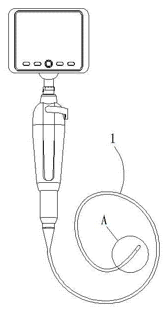
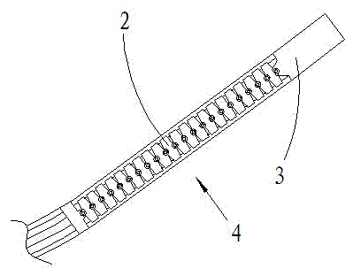
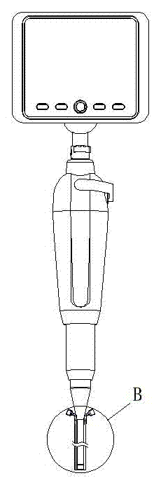
[0022] Embodiment: A sleeve tube for flexible laryngoscope with adjustable insertion direction, such as figure 1 , figure 2 As shown, it includes a hose 1, a plurality of rotating rings 2, and a camera 3. A plurality of rotating rings 2 are hingedly connected in pairs to form a keel portion 4 that can adjust the curvature. The hose 1 is connected to the camera 3 through the keel portion 4; image 3 , Figure 4 As shown, the outer peripheral side of the hose 1, the keel part 4, and the camera 3 is sleeved with a sleeve 5, and the end face of the sleeve 5 made of a flexible transparent material close to the camera 3 is a closed end, and the end face of the camera 3 shooting end is closed. Abutting against the inner end surface of the closed end of the casing 5, the outer peripheral surface of the camera 3 is provided with an annular groove 8, and the inner peripheral surface of the sleeve 5 is provided with an annular protrusion 9 matching the annular groove 8. The other end ...


PUM


Abstract

The invention discloses a sleeve pipe for an inserting-direction-adjustable flexible pipe laryngoscope. The sleeve pipe comprises a flexible pipe, a plurality of rotating rings and a camera. The rotating rings are hinged to each other in a pairing mode in sequence to form a curvature-adjustable keel part. The flexible is connected with the camera through the keel part. Sleeve pipes are connected to the periphery sides of the flexible pipe, the keel part and the camera in a sleeved mode. One end faces, close to the camera, of the sleeve pipes made of flexible transparent materials are sealed ends. The end face of a shooting end of the camera is in abutting connection with the inner end faces of the sealed ends of the sleeve pipes. A clamping-connecting structure is arranged between the camera and the sleeve pipes. The other ends of the sleeve pipes are opening ends. Through channels which extend in the length direction are arranged in the pipe walls of the sleeve pipes. The sleeve pipe has the advantages that a flexible pipe laryngoscope inserting part can be used repeatedly, cross infection of a patient can be avoided, and meanwhile when pipe inserting is completed, medicine feeding or phlegm sucking or blood stain sucking can be carried out according to needs.

Description

technical field [0001] The invention belongs to the technical field of medical instruments, in particular to an auxiliary product for a flexible laryngoscope whose insertion direction can be adjusted. Background technique [0002] Laryngoscopes, as a necessary instrument in the anesthesiology department, emergency department and laryngology department of the hospital, have been used more and more widely. In order to arbitrarily adjust the radius of curvature of the insertion end of the hose according to the actual situation during laryngeal anesthesia or diagnosis and treatment, so that the doctor can quickly find the position of the glottis or the patient to complete the insertion anesthesia or diagnosis and treatment in time, reduce the pain of the patient, and improve the doctor's work efficiency, the company submitted a patent application with the announcement number CN103393394A to the Patent Office of the State Intellectual Property Office on July 30, 2013. ", the tec...

Claims


Application Information

Patent Timeline
Patent Type & Authority Applications(China)
IPC IPC(8): A61B1/267A61B1/005A61B1/04A61M1/00
Inventor 王天星夏棋强李日照朱威灵黄闻晶王卫东李岳胜
Owner ZHEJIANG UE MEDICAL
Why Eureka
Try Eureka