

Mixing device, discharge device provided therewith, and discharge method
a technology of discharge device and mixing device, which is applied in the direction of mixing, rotary stirring mixer, transportation and packaging, etc., can solve the problems of inability to discharge, liquid mixed with solid particles is discharged in a non-uniform state, and is difficult to hold a uniformly mixed sta
- Summary
- Abstract
- Description
- Claims
- Application Information
AI Technical Summary
Benefits of technology
Problems solved by technology
Method used
Image

Examples
first embodiment
[0040](1) Mixing Device
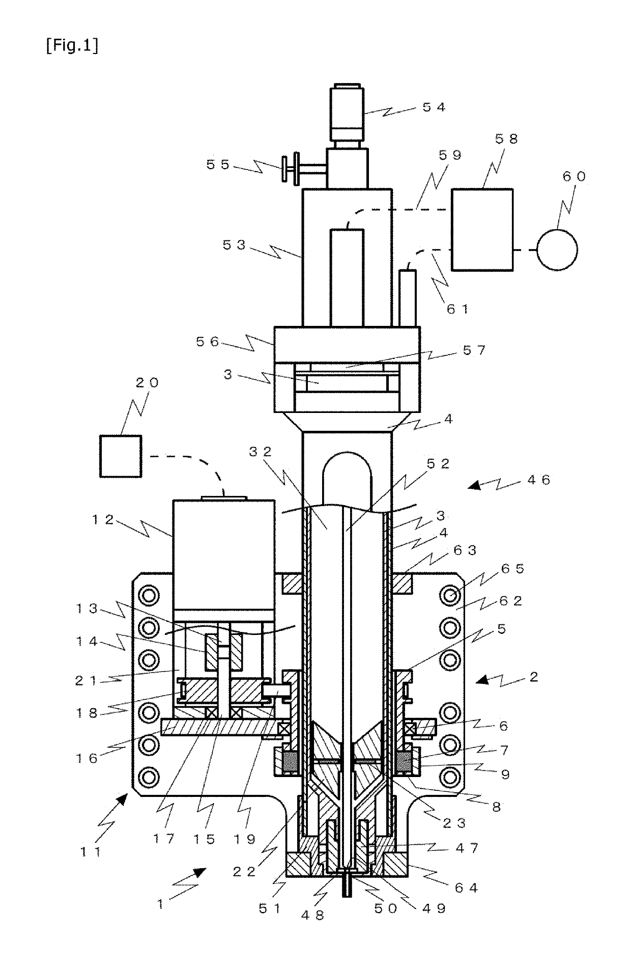
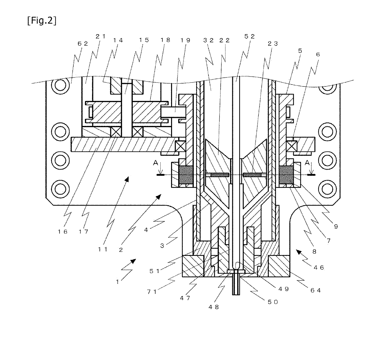
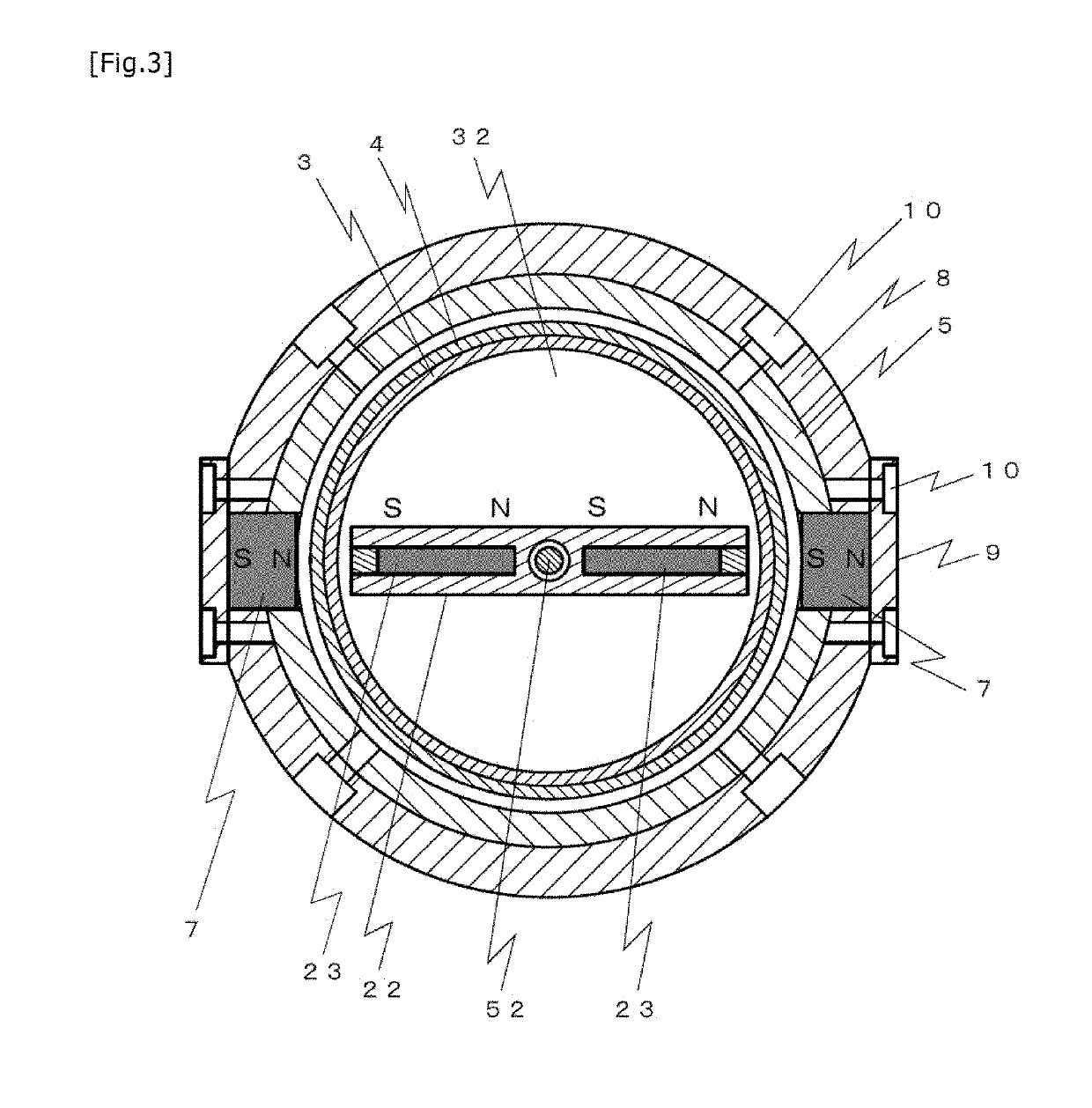
[0041]FIG. 1 illustrates, in a way partially sectioned in principal parts, a discharge device provided with a mixing device according to a first embodiment, FIG. 2 is an enlarged sectional view of a portion including the mixing device illustrated in FIG. 1, and FIG. 3 is a sectional view taken along A-A in FIG. 2. FIG. 4 illustrates a stirrer used in the mixing device according to the first embodiment. Specifically, FIG. 4(a) is a perspective view, and FIG. 4(b) is a side view looking at the stirrer from a direction denoted by an arrow B in FIG. 4(a). In the following, the side including a stroke adjustment mechanism 54 in FIG. 1 is called the upper side, and the side including a nozzle 50 is called the lower side in some cases for convenience in explanation.
[0042]A mixing device 1 according to this embodiment includes, as main components, a stirrer holding mechanism 2, a rotation mechanism 11, and a stirrer 22.
[0043](Stirrer Holding Mechanism)
[0044]The stirre...
second embodiment
[0080]A second embodiment relates to a discharge device including a plurality of stirrers. Such a discharge device is suitable for the case where the vessel (syringe) communicating with the nozzle has a large capacity, or the case using a liquid mixed with particles that tend to precipitate.
[0081]In a mixing device 1 according to this embodiment, a plurality of stirrers can be disposed in the lengthwise direction of the syringe 3 and can be rotated because magnetic forces are exerted on the syringe 3 from the lateral side instead of being exerted on the syringe 3 from below. FIG. 6 illustrates, in a way partially sectioned in principal parts, the discharge device provided with the mixing device according to the second embodiment. In the following, only different features from those in the first embodiment are described, and duplicate description of the same features is omitted.
[0082]The mixing device 1 according to this embodiment includes three stirrers 22 disposed within the vesse...
third embodiment
[0085]A third embodiment relates to an air type discharge device that discharges a liquid in the vessel (syringe) 3 by the action of compressed gas. FIG. 7 illustrates, in a way partially sectioned in principal parts, the discharge device provided with a mixing device according to the third embodiment. In the following, only different features from those in the first embodiment are described, and duplicate description of the same features is omitted.
[0086]A discharge device 67 according to this embodiment does not include the plunger 52 and the components associated with the plunger, and it includes, as main components, the vessel 3, the nozzle 50, the discharge controller 58 that adjusts pressure of the compressed gas supplied from the compressed gas source 60 to a desired level and then supplies the compressed gas, and the adapter 69 that supplies the compressed gas under the adjusted pressure to the vessel 3 through a tube 68. The discharge device 67 discharges the liquid by appl...
PUM
| Property | Measurement | Unit |
|---|---|---|
| angle | aaaaa | aaaaa |
| magnetic force | aaaaa | aaaaa |
| thickness | aaaaa | aaaaa |
Abstract
Description
Claims
Application Information