Hydraulic valve system of a parking lock device

a technology of hydraulic valve system and parking lock, which is applied in mechanical equipment, braking systems, transportation and packaging, etc., can solve the problems the failure of the system to engage the parking lock after the vehicle shutdown, and the inability to hold the locking device in the disengaged operating state in the presence of low system pressure, etc., and achieves high spontaneity.

Active Publication Date: 2019-06-11
ZF FRIEDRICHSHAFEN AG
View PDF9 Cites 0 Cited by
  • Summary
  • Abstract
  • Description
  • Claims
  • Application Information

AI Technical Summary

Benefits of technology

[0009]In example embodiments, the present invention provides an electrohydraulic transmission control system having a parking lock valve, by which a transmission can be operated in an as far as possible optimized manner in terms of efficiency and with high spontaneity, and by which a parking lock can, even in the event of a transition to emergency operation, be transferred into the engaged operating state within defined operating times.

Problems solved by technology

If a fault arises in the transmission system during operation with the parking lock disengaged, which fault leads to the deactivation of the electrical supply of the transmission actuators, the automatic transmission switches to so-called hydraulic emergency operation.
This however has the result that the self-holding pressure of the parking lock valve lies below the minimum system pressure level, because otherwise, the parking lock cannot, in the presence of low system pressures, be held any longer in the disengaged operating state by the system pressure.
In the event of a transition to hydraulic emergency operation, it is additionally the case that the electromechanical locking mechanism of the parking lock is deactivated, with the result that inadequate hydraulic actuation of the parking lock device during emergency operation results in an immediate actuation of the parking lock device in the direction of the engaged operating state.
In particular in the presence of low operating temperatures, the leakage volume flows of the primary pressure circuit are very small.
Since the minimum discharge pressure of the hydraulic fluid volume accumulator is above the self-holding pressure threshold of the parking lock valve, the engagement of the parking lock after the shutdown of the vehicle is delayed, however, to an undesired extent.

Method used


Image

  • Hydraulic valve system of a parking lock device
  • Hydraulic valve system of a parking lock device
  • Hydraulic valve system of a parking lock device

Examples


Embodiment Construction

[0040]Reference will now be made to embodiments of the invention, one or more examples of which are shown in the drawings. Each embodiment is provided by way of explanation of the invention, and not as a limitation of the invention. For example, features illustrated or described as part of one embodiment can be combined with another embodiment to yield still another embodiment. It is intended that the present invention include these and other modifications and variations to the embodiments described herein.

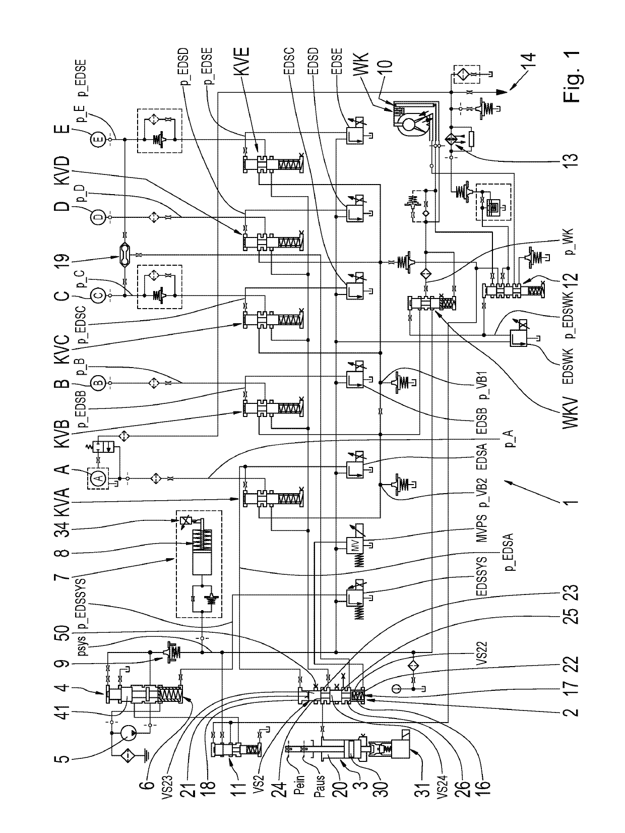
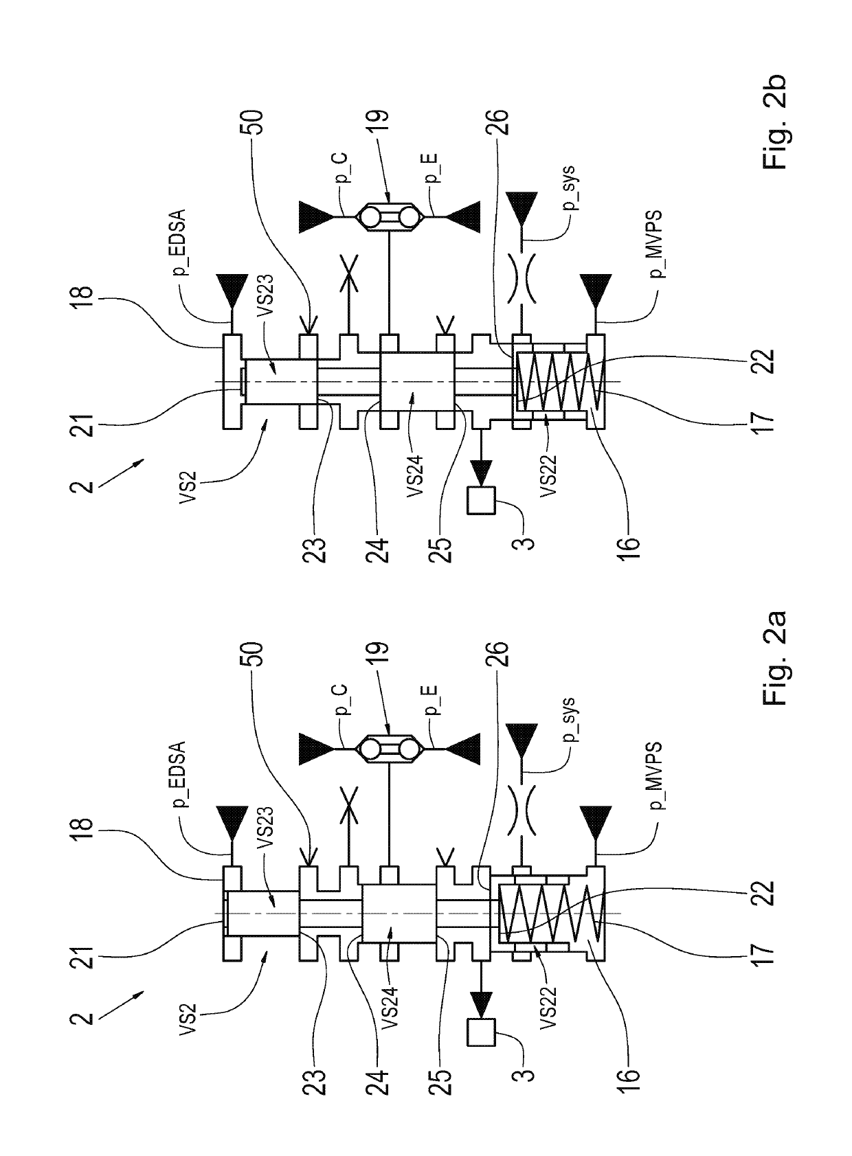
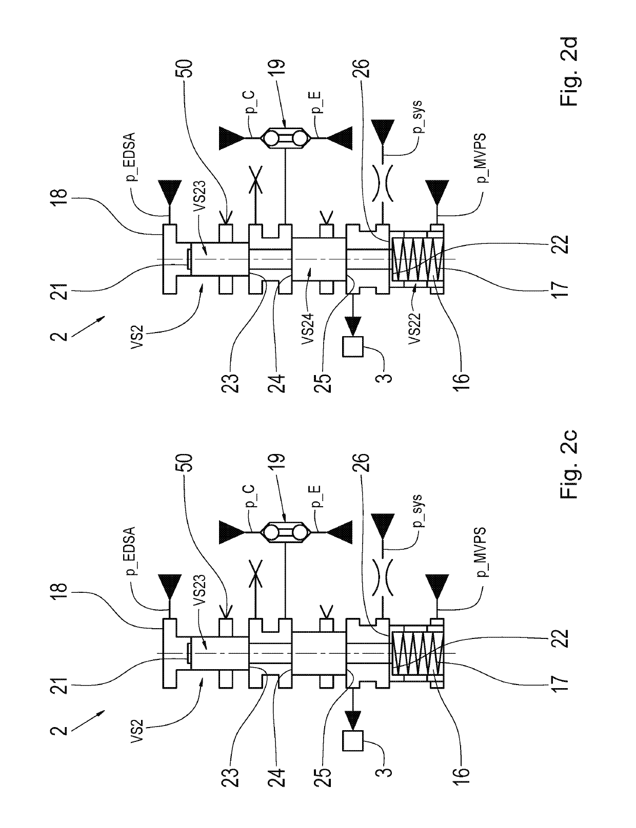
[0041]FIG. 1 shows a hydraulic layout of an embodiment of an electrohydraulic transmission control system 1 having a parking lock valve 2, by which a parking lock cylinder 3 can be charged with an actuation or system pressure p_sys. The electrohydraulic transmission control system 1 is provided for actuating a transmission, preferably an automatic transmission, in which eight ratios for forward travel and at least one ratio for reverse travel can be realized. During the realizatio...


PUM


Abstract

An electrohydraulic transmission control system (1) includes a parking lock valve (2). The electrohydraulic transmission control system (1) is configured such that, during normal operation of the electrohydraulic transmission control system (1) in which at least one electrohydraulic pressure adjuster (EDSSYS) is actuatable with current, the parking lock valve (2) can be held in a defined operating state in which an actuation pressure (p_sys) acts on a parking lock cylinder (3) above a normal pressure level. The electrohydraulic transmission control system (1) is configured such that, during emergency operation of the electrohydraulic transmission control system (1) in which the at least one electrohydraulic pressure adjuster (EDSSYS) is not fed with current and the actuation pressure (p_sys) is at least temporarily set to an emergency pressure level higher than the normal pressure level by the at least one pressure source (7), a pressure level of the actuation pressure (p_sys) that holds the parking lock valve (2) in the defined operating state corresponds at least approximately to the emergency pressure level.

Description

FIELD OF THE INVENTION[0001]The invention relates generally to an electrohydraulic transmission control system having a parking lock valve.BACKGROUND[0002]The applicant's patent application DE 10 2015 211 298.5, which does not constitute a prior publication, discloses a hydraulic system of an automatic transmission having a hydraulically actuable parking lock unit. A parking lock valve is configured with multiple valve pockets formed in the region of a valve housing, by which an actuation pressure of the parking lock unit, which actuation pressure prevails in a manner dependent on a supply pressure, can be applied to said parking lock unit. The valve pockets can be placed in operative connection with one another, or separated from one another, by a valve slide which is longitudinally displaceable in the valve housing. The valve slide is spring-loaded in the direction of a first axial position which corresponds to a first operating state of the parking lock valve and in which, in tur...

Claims


Application Information

Patent Timeline
Patent Type & Authority Patents(United States)
IPC IPC(8): B60T13/66F16D63/00B60T1/00B60T1/06B60T13/68F16H63/34
CPCF16H63/3483B60T1/005F16D63/006B60T13/662B60T13/686B60T1/062
Inventor HERRMANN, MARKUSSCHMIDT, THILOROLSER, TOBIAS
Owner ZF FRIEDRICHSHAFEN AG
Why Eureka
Try Eureka