Motor vehicle heat exchanger system

A technology of heat transfer system and motor vehicle, applied in the field of motor vehicle heat transfer system, can solve problems such as pressure drop, and achieve the effect of high spontaneity

Inactive Publication Date: 2016-11-23
BENTELER AUTOMOBILTECHNIK GMBH
View PDF7 Cites 0 Cited by
  • Summary
  • Abstract
  • Description
  • Claims
  • Application Information

AI Technical Summary

Problems solved by technology

As a result, adverse effects that can occur when the working media mix and lead to a pressure drop are to be avoided

Method used


Image

  • Motor vehicle heat exchanger system
  • Motor vehicle heat exchanger system
  • Motor vehicle heat exchanger system

Examples


Embodiment Construction

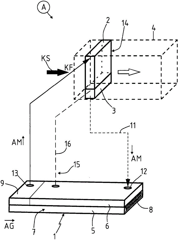
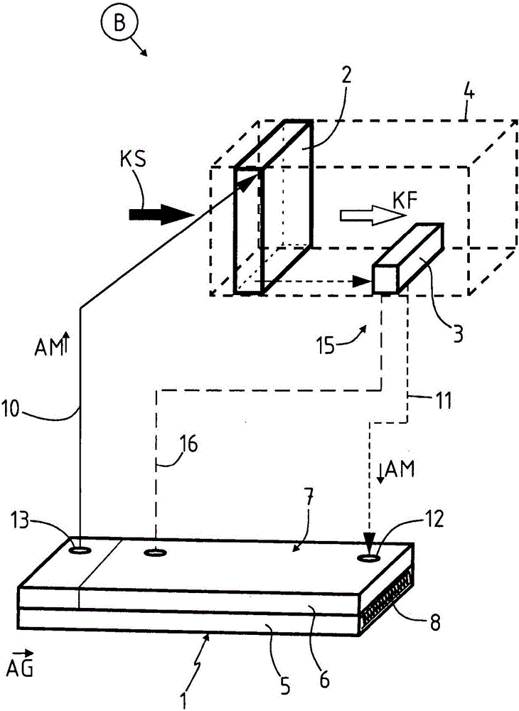
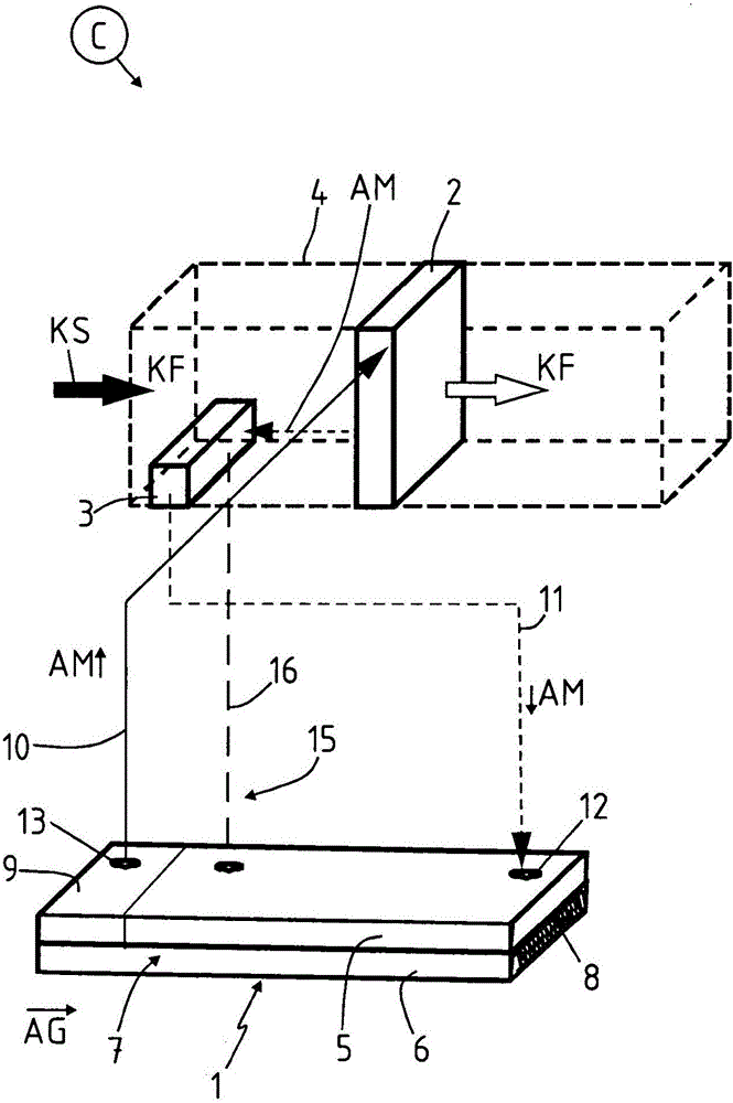
[0037] Corresponding components or system parts in the Figures 1 to 3 The same reference numerals are provided in .

[0038] Figures 1 to 3 A motor vehicle heat transfer system A, B, C is shown schematically and technically simplified in each case.

[0039]Each motor vehicle heat transfer system A, B, C has a closed circuit for the working medium AM and comprises an evaporator 1 for vaporizing the working medium AM and a condenser 2 for condensing the vaporous working medium AM. A compensation vessel 3 is provided between the condenser 2 and the evaporator 1 . The carburetor 1 is integrated into the exhaust gas flow AG of the internal combustion engine of the motor vehicle. Said condenser 2 is charged into the cooling fluid flow KS. The cooling fluid KF can be a gas, in particular air, or also a liquid, such as oil. The condenser 2 is impinged on the cooling fluid KF in the cooling fluid flow KS and the cooling fluid KF flows through it or flows around or through it. T...


PUM


Abstract

A motor vehicle heat exchanger system (B) with a closed circuit for an operating medium (AM) is disclosed, which includes an evaporator for evaporating the operating medium (AM) and a condenser (2) for allowing cooling fluid (KF) to flow through and condensing the vaporous operating medium (AM). Between the condenser (2) and the evaporator (1) a compensation container (3) for receiving the operating medium (AM) is integrated. The compensation container (3) is arranged in the cooling fluid stream (KS) and can be cooled by the cooling fluid stream (KS). Specifically, the compensation container (3) is integrated to the condenser (2) and form a structural unit with the condenser (2).

Description

technical field [0001] The invention relates to a heat transfer system for a motor vehicle according to the features of the preamble of claim 1 . Background technique [0002] The utilization of the heat energy lost in the exhaust gas of the internal combustion engine of a motor vehicle offers various options for increasing the efficiency of the motor vehicle. In this regard, the use of exhaust gas heat for heating the passenger compartment offers the possibility of omitting additional heating measures and thereby reducing fuel consumption. Exhaust heat can likewise be used to accelerate the thermal operation of motor vehicle drive train components. As a result, the mechanical power loss during the warm-up phase can be reduced, thereby reducing the engine load and engine consumption. [0003] The recovery of the waste heat generated during the engine-like combustion thus offers great potential for fuel savings and can contribute to an increase in the driving and operating ...

Claims


Application Information

Patent Timeline
Patent Type & Authority Applications(China)
IPC IPC(8): F25B41/00F25B39/04F02G5/02F28D15/02F25B41/40
CPCF02G5/02F25B39/04F25B41/00F28D15/0266F25B2339/042F01N5/02F28D15/043F22B1/1807F25B2339/044F25B2400/16Y02E20/30Y02T10/12F25B43/006
Inventor F·鲁比特舍克S·普日拜尔斯基T·迪迈尔
Owner BENTELER AUTOMOBILTECHNIK GMBH
Why Eureka
Try Eureka