High pressure fuel gas pump

a gas pump and high-pressure technology, applied in the direction of piston pumps, marine propulsion, vessel construction, etc., can solve the problems of reducing service life, requiring massive investment costs, and reducing the service life of fuel supply systems currently available for high-pressure cryogenic lng, so as to achieve the effect of prolonging service life and being easy to maintain

Active Publication Date: 2019-06-25
ACD
View PDF15 Cites 0 Cited by
  • Summary
  • Abstract
  • Description
  • Claims
  • Application Information

AI Technical Summary

Benefits of technology

[0008]Embodiments of the present invention seek to provide a high-pressure pump for LNG / LH2 / LN2 / LAR and other uses which simplifies and reduces the size of current systems, and has a life span increase of 200-500%, significantly reduced operating costs, and greater ease of maintainability.
[0010]An exemplary method for pumping of high-pressure cryogenic fuel from a fuel source to provide a smooth, pulse-free output comprises providing a pumping system having a plurality of linear pumps each including in series an upper power end and a lower fluid end. The power end has a linear-actuated drive system terminating in a drive shaft that linearly reciprocates along an axis, and the power end drive system of each pump is independently controllable via software contained within a multi-axis electronic controller. Beneficially, the lower fluid end has no packing seals so as to reduce wear and extend operating life. The fluid end of each linear pump has a piston coupled to the drive shaft of the power end so as to linearly reciprocate within a fluid cylinder, and the fluid cylinders of the plurality of linear pumps are all mounted together and have outlet flow passages leading to a common outlet port. The method includes supplying cryogenic fuel from a fuel source to inlet passageways of the fluid cylinders of each of the plurality of linear pumps. The drive system is actuated to displace the drive shaft and coupled piston of each of the plurality of linear pumps so as to pull cryogenic fuel into the respective fluid cylinders and expel the cryogenic fuel through the outlet flow passages to the common outlet port. Coordinating actuation of the separate linear pumps results in a pulse-free output pressure profile. Finally, a sealed housing is provided around one or more of the linear pumps, the housing being sealed to contain any of the high-pressure cryogenic fuel that escapes from within the fluid cylinder.
[0013]There may be a single outer housing sealed around a plurality of the linear pumps. In that case, a common lower manifold plate is preferably provided to which each of the linear pumps mounts and in which the lower flow passages of each linear pump is formed. The single outer housing may comprise an upper housing generally surrounding the upper power end and secured to a lower housing generally surrounding the lower fluid end, and wherein there are no conduits attached to the upper housing so that the upper housing may be easily removed for servicing the power end drive system. Alternatively, there is a separate outer housing sealed around each one of the plurality of the linear pumps, and further including a common lower manifold plate to which each of the linear pumps mounts and in which the lower flow passages of each linear pump is formed.

Problems solved by technology

Global energy demands continue to rise year after year as existing oil reservoirs become depleted and the search for replacements spreads to deeper parts of the ocean, requiring massive investment costs.
The fuel supply systems currently available for high-pressure cryogenic LNG are susceptible to leakage or failure from various mechanical sources.
Such leaks reduce the service life and increase the maintenance load for LNG pumping equipment.
In the same vein, other industrial gas service pumps used for liquid nitrogen (LN2), liquid argon (LAR) and liquid hydrogen (LH2) are also susceptible to leakage and attendant maintenance problems.

Method used


Image

  • High pressure fuel gas pump
  • High pressure fuel gas pump
  • High pressure fuel gas pump

Examples


Embodiment Construction

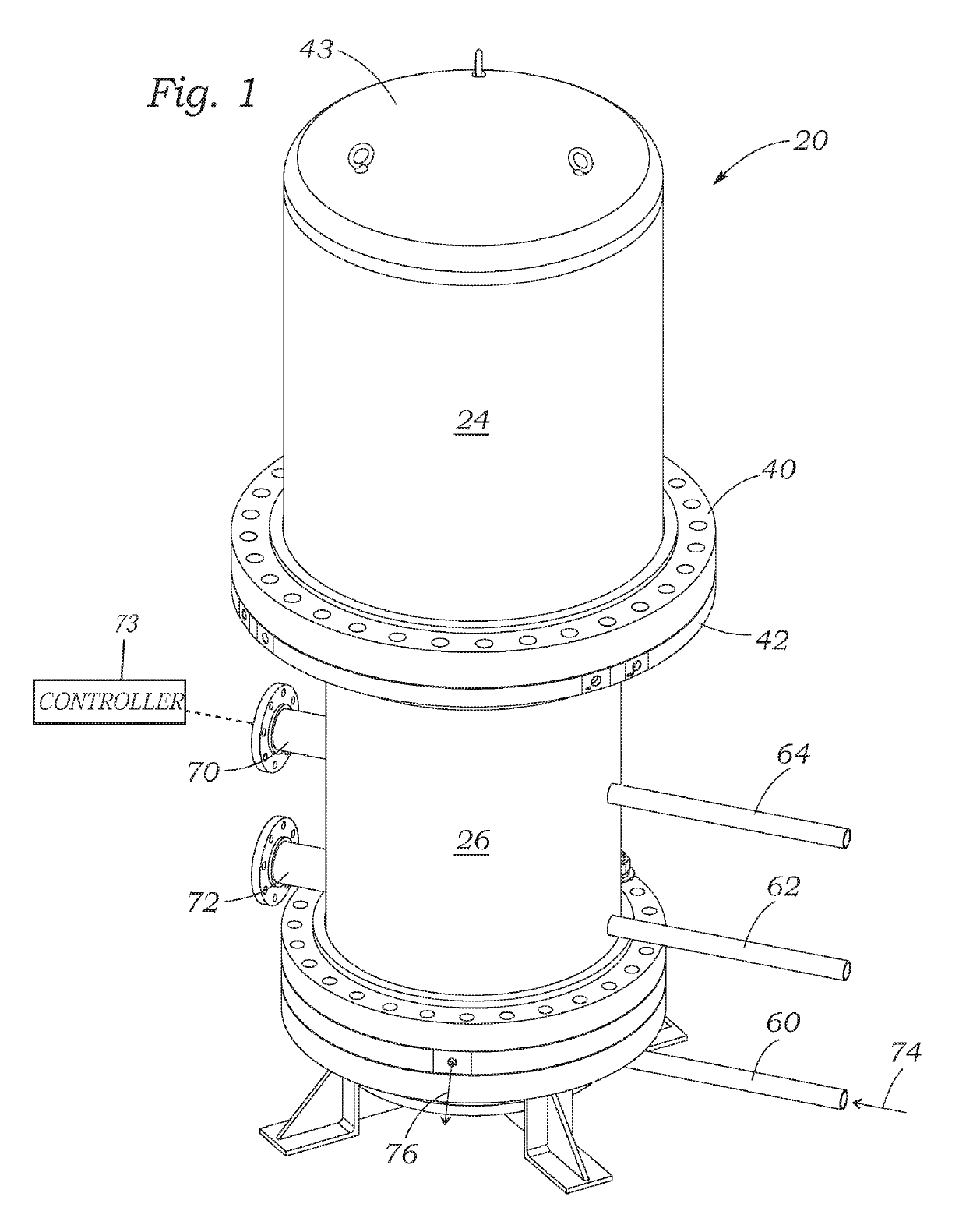
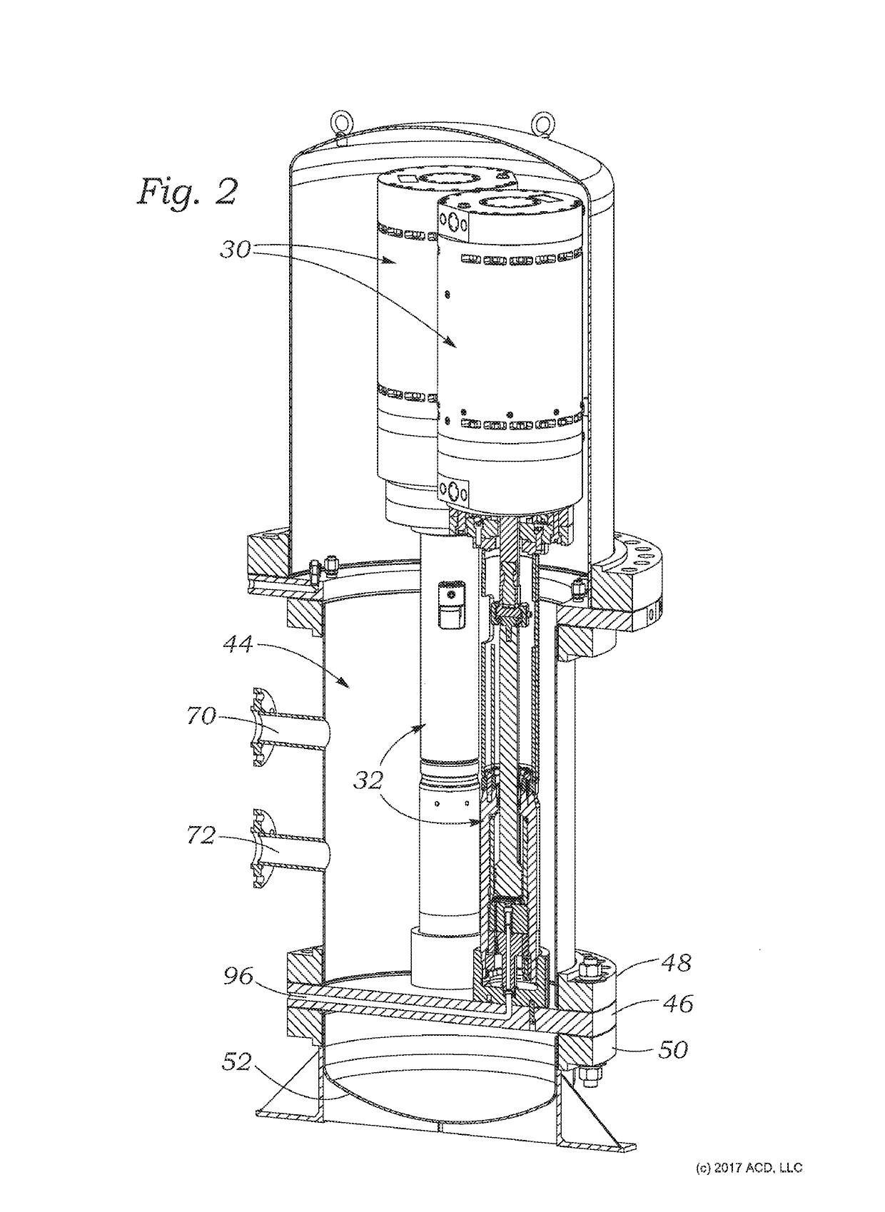
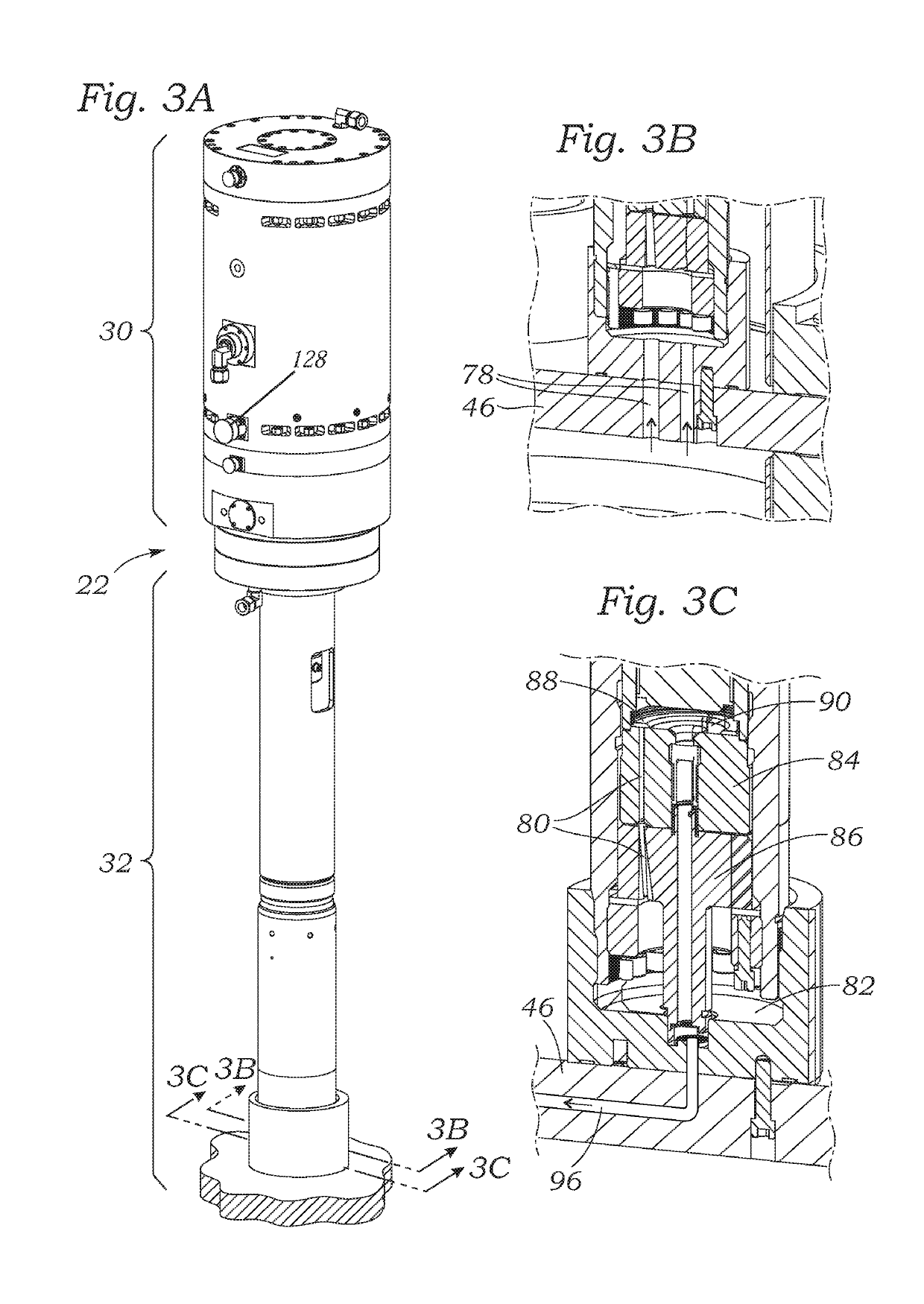
[0024]The present application discloses an improved modular, linearly actuated high-pressure LNG / LH2 / LN2 / LAR pump system especially for use in marine applications with high-pressure fuel systems. The term “linear actuation” refers to a system that does not rely on the traditional mode of converting rotational motion to linear motion, which often creates intense vibrations, and thus linear actuation mechanisms smooth out the resulting power profile. Of course, the presently disclosed pump system may be used in transportation applications other than marine with similar benefits, including trains, trucks, and buses. Other non-transportation areas in which the high-pressure LNG pump is useful include industrial gas and alternative fueling applications. Additionally, although liquid natural gas for fueling is the primary commodity that can be pumped using the present systems, liquid nitrogen, hydrogen, argon, and other cryogenic liquid hydrocarbons may also be processed using the pumps d...


PUM


Abstract

There is disclosed a modular, linearly actuated high-pressure pump for use in various applications with high-pressure fuel systems, in particular liquid cryogenic fuels such as Natural Gas, Hydrogen, Nitrogen and Argon (LNG / LH2 / LN2 / LAR). The pump utilizes linear actuation which smooths out the power profile. There are no dynamic seals which prevents failure from leakage. The primary benefit of a smooth, no pulse output and lack of dynamic seals is a longer life of the pump. Marine fuel systems that utilize cryogenic LNG are a primary application.

Description

RELATED APPLICATIONS[0001]The present application claims priority under 35 U.S.C. § 119 to U.S. Provisional Patent Application No. 62 / 380,855, filed Aug. 29, 2016.NOTICE OF COPYRIGHTS AND TRADE DRESS[0002]A portion of the disclosure of this patent document contains material which is subject to copyright protection. This patent document may show and / or describe matter which is or may become trade dress of the owner. The copyright and trade dress owner has no objection to the facsimile reproduction by anyone of the patent disclosure as it appears in the Patent and Trademark Office patent files or records, but otherwise reserves all copyright and trade dress rights whatsoever.BACKGROUNDField[0003]This disclosure relates to a high-pressure gas pump especially for marine service and, more particularly, to a modular, linearly actuated high-pressure pump for use in applications with high-pressure fuel systems such as marine, industrial gas and alternative energy fuel systems, for instance ...

Claims


Application Information

Patent Timeline
Patent Type & Authority Patents(United States)
IPC IPC(8): F02M21/02F04B49/06F04B15/08F04B17/04F04B11/00F04B9/02F04B23/02
CPCF02M21/0218F02M21/0245F04B9/02F04B11/005F04B15/08F04B23/026F04B49/065F04B17/042Y02T10/32F02M21/02F04B2015/081B63H21/38Y02T10/30F05B2210/12
Inventor WELLS, MICHAEL
Owner ACD
Why Eureka
Try Eureka