Radio remote control for photographic equipment

a technology for remote control and photographic equipment, applied in the field of photographic equipment, can solve the problem of inability to replace the batteries in the tx, and achieve the effects of simplifying and reducing the size of the rx, and consuming much less power

Inactive Publication Date: 2006-12-07
TAMRAC
View PDF10 Cites 46 Cited by
  • Summary
  • Abstract
  • Description
  • Claims
  • Application Information

AI Technical Summary

Benefits of technology

[0014] The advantage of this power-management circuit is that it also allows the RX to consume much less power, eliminate the power switch and external power jack, and therefore, simplify and reduce the size of the RX.
[0015] The advantage of reducing the reduced size of the RX is that it is less obtrusive for the user, and requ

Problems solved by technology

Since it automatically returns to a sleep mode, it makes it impossible

Method used


Image

  • Radio remote control for photographic equipment
  • Radio remote control for photographic equipment
  • Radio remote control for photographic equipment

Examples


Embodiment Construction

[0025] Although specific embodiments of the present invention will now be described with reference to the drawings, it should be understood that such embodiments are by way of example only and merely illustrative of but a small number of the many possible specific embodiments which can represent applications of the principles of the present invention. Various changes and modifications obvious to one skilled in the art to which the present invention pertains are deemed to be within the spirit, scope and contemplation of the present invention as further defined in the appended claims.

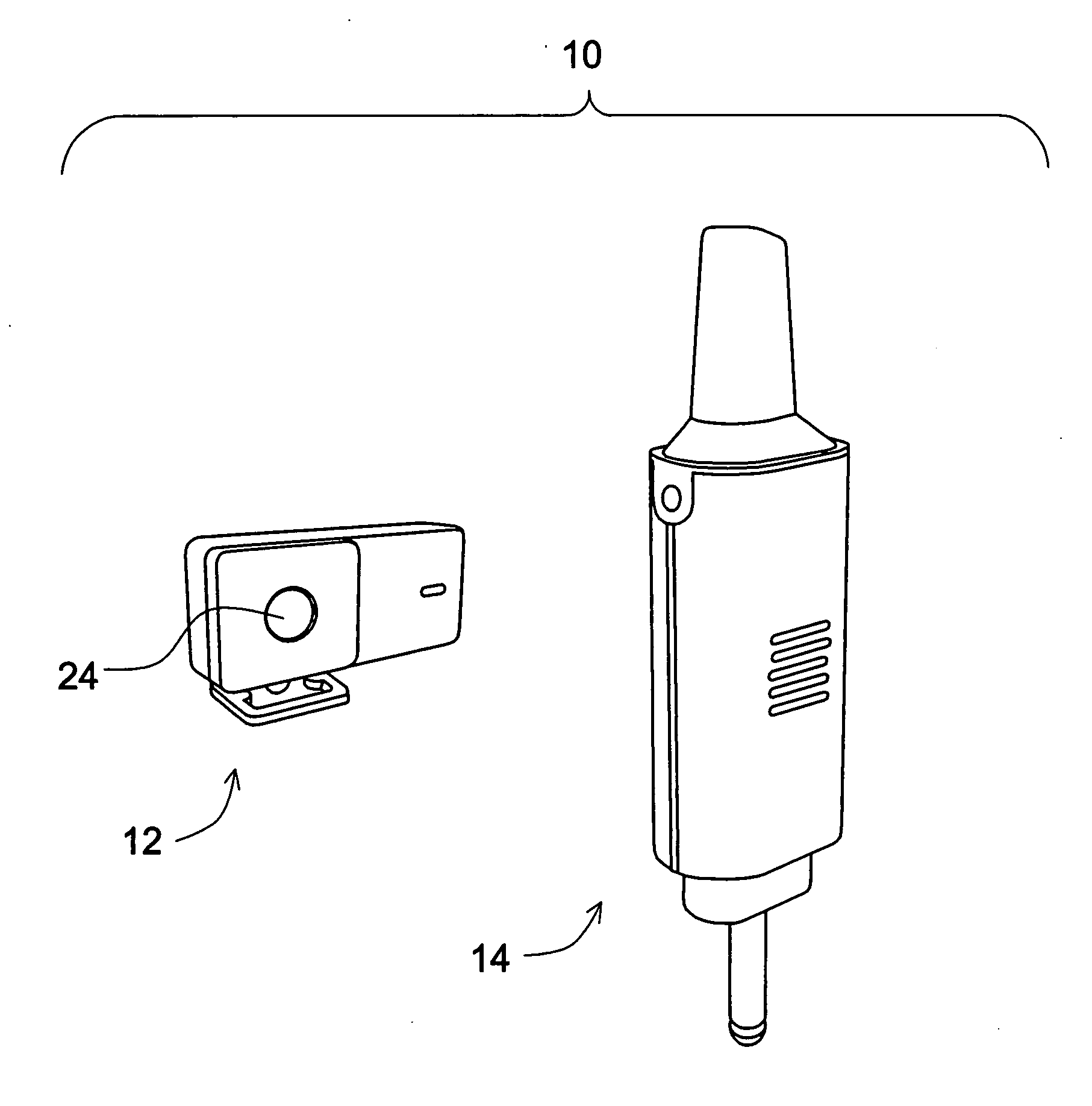
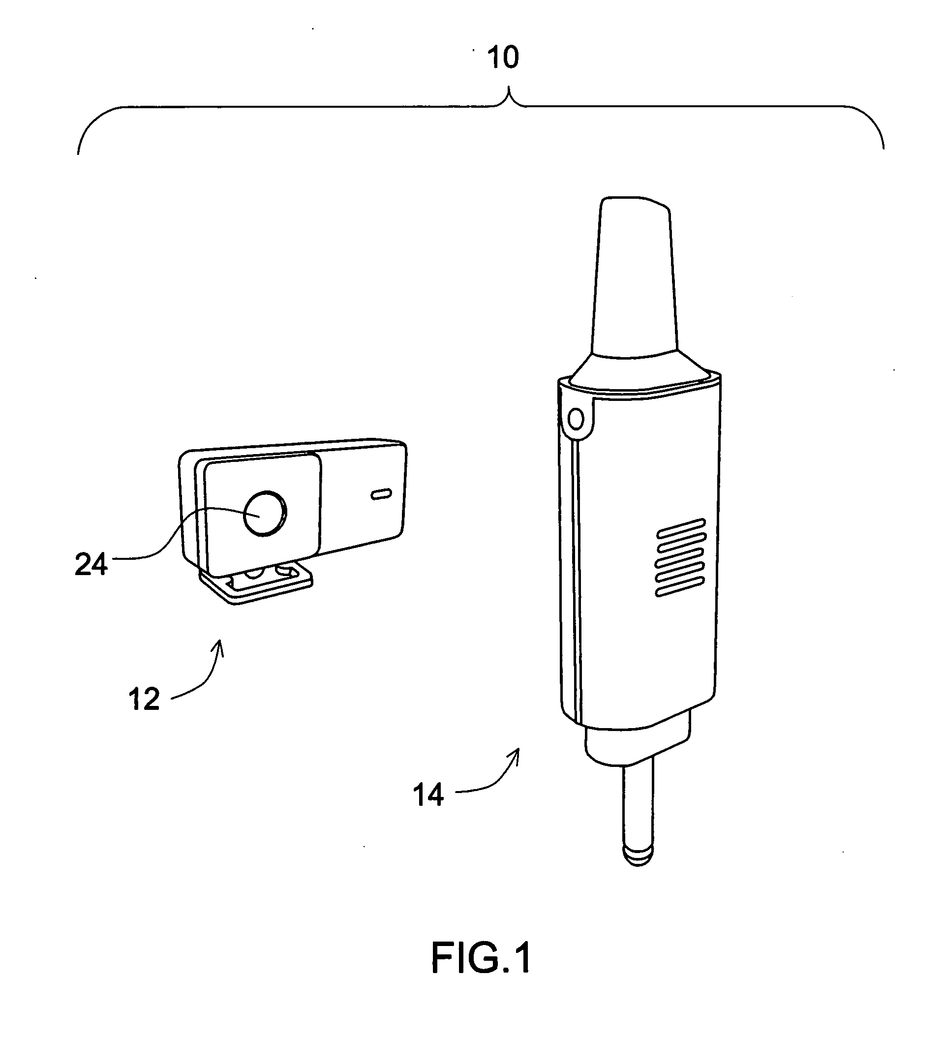
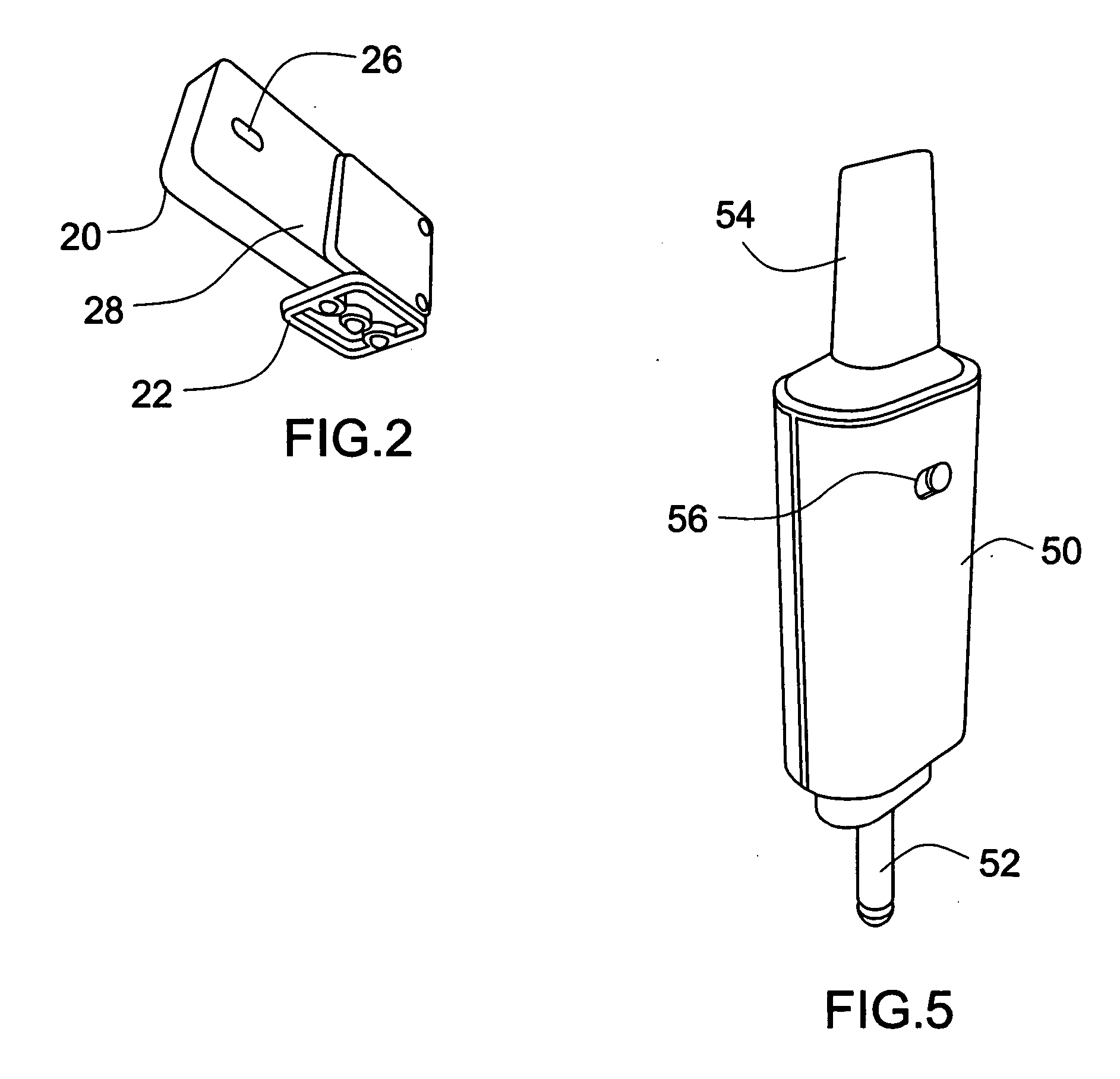
[0026] Described generally, the present invention is a radio sync system to be used between local and remote photographic equipment. The radio sync system includes a transmitter unit and a receiver unit.

[0027] The transmitter unit has a hotfoot for connection with a local photographic equipment and a housing for containing its internal electronics including a microprocessor, an input signal detector, a ...


PUM


Abstract

A radio sync system for photographic equipment including a transmitter unit and a receiver unit. The transmitter unit utilizes a power-management scheme for keeping the transmitter unit in a low-power stand-by state except when an RF signal needs to be transmitted, and returning the transmitter unit back into the low-power stand-by state within a predefined short period of time after transmitting the RF signal. The receiver unit utilizes a power-sensing scheme for keeping the receiver unit in a low-power stand-by state when it is not connected to a remote photographic equipment or the remote photographic equipment is powered off but turning the receiver unit on when it is connected to a remote photographic equipment and the remote photographic equipment is powered on such that when an RF signal is received, the receiver unit can send a command signal to operate the remote photographic equipment.

Description

BACKGROUND OF THE INVENTION [0001] 1. Field of the Invention [0002] The present invention relates to the fields of photographic equipment and particularly radio transmitters and receivers for photographic equipment. [0003] 2. Description of the Prior Art [0004] Radio transmitters and receivers have been used for photographic equipment, including those specifically designed transmitters and receivers that allow users to trigger photographic strobe lighting remotely. [0005] Professional photographers often use a momentary flash form strobe lighting to illuminate their subjects. One of the requirements for a flash is that it must occur precisely when the camera shutter is open, i.e., be “synchronized” with the shutter. [0006] The most common method for synchronizing a strobe to the shutter is a sync cable which electrically connects an output signal from a camera to an input port of the strobe unit. An alternative sync method is to use a wireless arrangement for transmitting the camera...

Claims


Application Information

Patent Timeline
IPC IPC(8): G03B17/00
CPCG03B9/70G03B15/03G03B15/0473H04N5/23241H04N5/2256H04N5/23203G03B2215/0557H04N23/56H04N23/66H04N23/661H04N23/651
Inventor MCNARY, WADE
Owner TAMRAC
Why Eureka
Try Eureka