
Flow rate sensor correction device, program for correction device, and correction method

a flow rate sensor and flow rate sensor technology, applied in the direction of liquid/fluent solid measurement, volume metering, instruments, etc., can solve the problem of flow rate error between the flow rate value y of actually flowing fluid, characteristic function f(x), and flow rate error except for the span flow rate value, so as to achieve good linearity and reduce flow rate error

Active Publication Date: 2019-06-25
HORIBA STEC CO LTD
View PDF4 Cites 0 Cited by
  • Summary
  • Abstract
  • Description
  • Claims
  • Application Information

AI Technical Summary

Benefits of technology

The present invention provides a flow rate sensor correction device, program for the correction device, and correction method that can improve the accuracy of flow rate sensors. The device can convert the initial flow rate characteristic function to a function with good linearity using a sensitivity correction value. The corrected function can then be matched with a standard function to reduce flow rate errors over the entire range of the sensor output value.

Problems solved by technology

Accordingly, for example, when directly using a standard flow rate characteristic function f(x) obtained by averaging the sensor characteristics of multiple flow rate sensors, an error occurs between a calculated flow rate value y and the flow rate value y of actually flowing fluid.
However, when making a correction as described above even though the linearity of an actual flow rate characteristic function F(x) is poor as illustrated in FIG. 7(c), the final flow rate characteristic function h(x) outputs a flow rate value y smaller than an actual flow rate value y from the zero point to the span point.
That is, a flow rate error occurs except for the span flow rate value.

Method used


Image

  • Flow rate sensor correction device, program for correction device, and correction method
  • Flow rate sensor correction device, program for correction device, and correction method
  • Flow rate sensor correction device, program for correction device, and correction method

Examples


Embodiment Construction

[0031]One embodiment of the present invention will be described with reference to drawings.

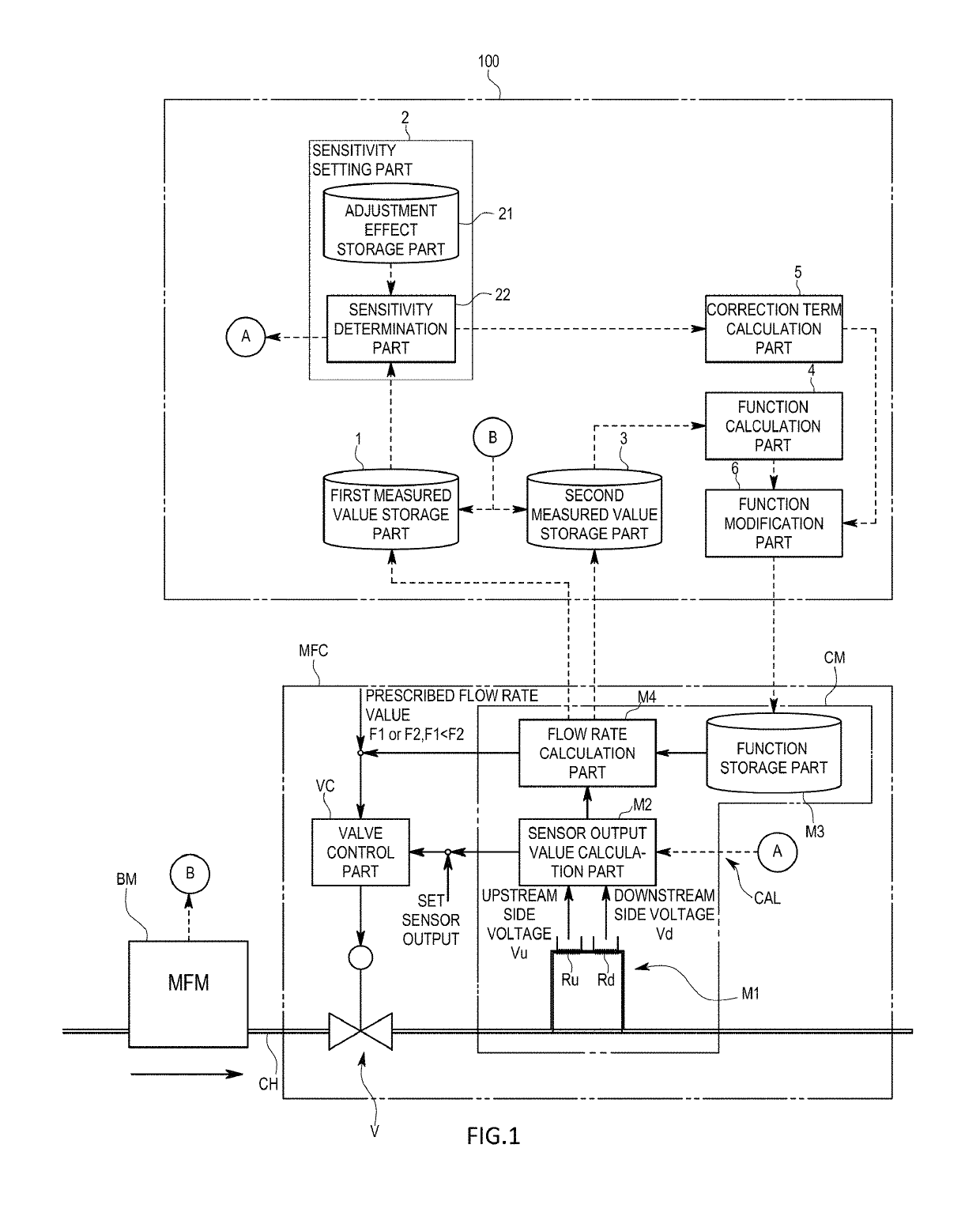
[0032]As illustrated in FIG. 1, a flow rate correction device 100 of the present embodiment is one used for making a correction to reduce a flow rate error over the entire range of a sensor output value x by accommodating the specific difference of, for example, a thermal type flow rate sensor at the time of factory shipment.

[0033]Note that the thermal type flow rate sensor as a correction target constitutes part of a thermal type mass flow controller MFC. That is, as illustrated in FIG. 1, the mass flow controller MFC is one including: a valve V provided in a flow path; the flow rate sensor adapted to measure a flow rate through the flow path; and a valve control part VC adapted to control the opening level of the valve V on the basis of an output from the flow rate sensor, in which these parts are packaged in one casing.

[0034]The details of the correction target flow rate sensor will be desc...


PUM


Abstract

In order to reduce a flow rate error over the entire range of a sensor output value even when the relationship between the sensor output value and a flow rate value is poor in linearity, a flow rate sensor correction device includes: a sensitivity setting part adapted to set a sensitivity coefficient on the basis of an initial value and a sensitivity correction value and adjust the sensitivity of the flow rate sensor; a function calculation part adapted to calculate a corrected flow rate characteristic function on the basis of a function correction value, which is determined on the basis of the flow rate value, and a standard flow rate characteristic function; and a function modification part adapted to make a function storage part store, as a flow rate characteristic function, a final flow rate characteristic function based on the corrected flow rate characteristic.

Description

TECHNICAL FIELD[0001]The present invention relates to a flow rate sensor correction device, a program for the correction device, and a correction method for correcting a flow rate characteristic function that converts a sensor output value x to a flow rate value y in a flow rate sensor.BACKGROUND ART[0002]For example, a thermal type flow rate sensor is configured to be able to measure a flow rate using the fact that between a flow rate and the quantity of heat removed from an object, a predetermined relationship exists. Specifically, as a sensor mechanism, two electrical resistive elements are provided in a flow path, voltages are controlled so as to keep the temperatures of the respective electrical resistive elements constant, and from the values of the respective voltages at the time, a sensor output value x having a predetermined relationship with a flow rate is calculated (see Patent Literature 1).[0003]In order to convert the sensor output value x to a flow rate value y, a flo...

Claims


Application Information

Patent Timeline
Patent Type & Authority Patents(United States)
IPC IPC(8): G01F1/68G01F25/00
CPCG01F1/68G01F25/0007G01F1/6965G01F15/04G01F1/69G01F1/696G01F25/10
Inventor OKANO, HIROYUKI
Owner HORIBA STEC CO LTD
Learn More