
Method and device for location detection

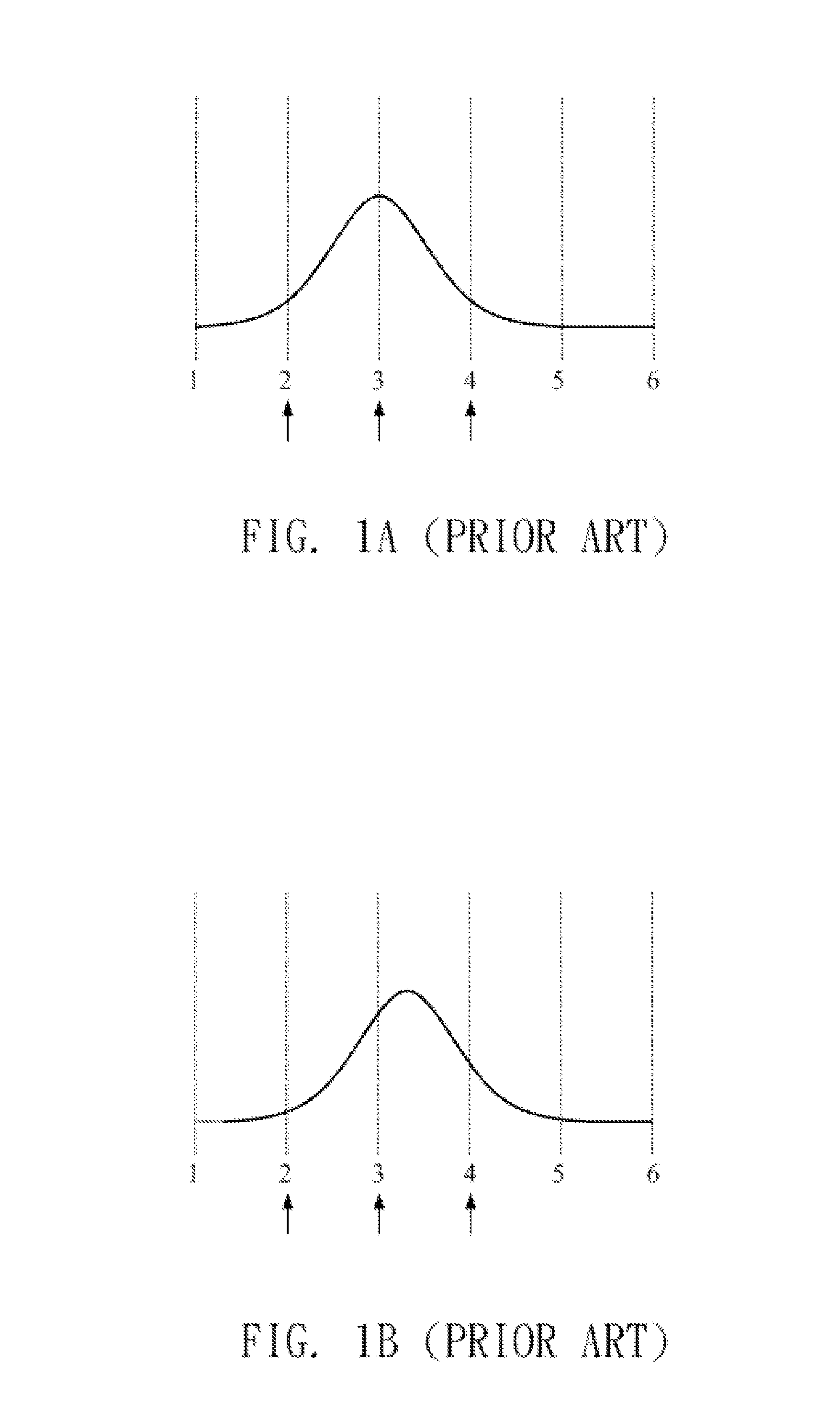
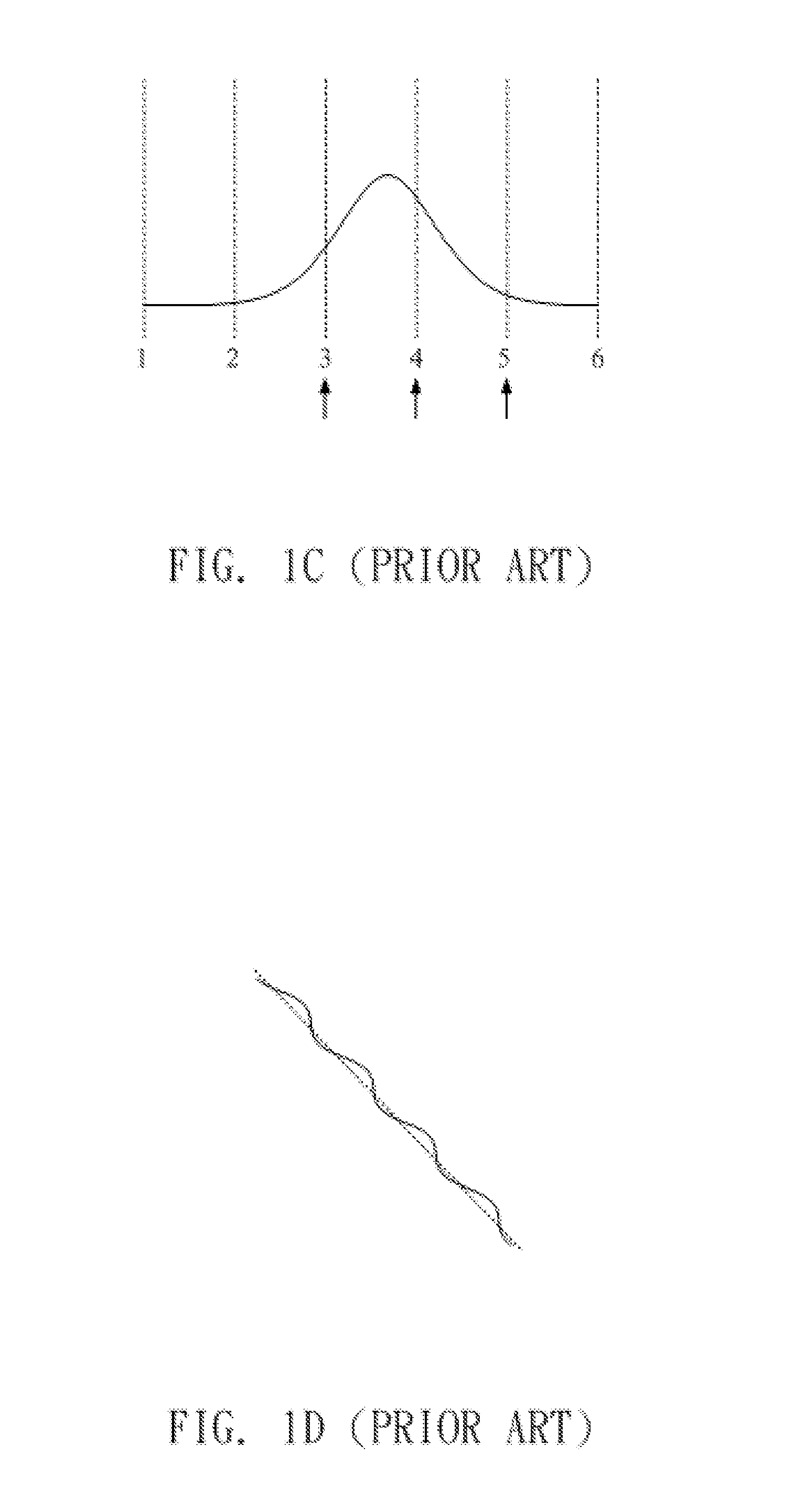
a technology of location detection and method, applied in the field of method and device for location detection, can solve the problems of poor linearity shown in fig. 1d, no appropriate structure and methods, long efforts made in vain, etc., and achieve the effect of reducing the problem of poor linearity

Active Publication Date: 2014-07-03
EGALAX EMPIA TECH INC
View PDF17 Cites 0 Cited by
  • Summary
  • Abstract
  • Description
  • Claims
  • Application Information

AI Technical Summary

Benefits of technology

The technical effect of this patent is to reduce the impact of the highest value during the generation of coordinate data, to improve linearity.

Problems solved by technology

As a result, poor linearity shown in FIG. 1D will occur.
In order to solve these problems, efforts have long been made in vain, while ordinary products and methods offering no appropriate structures and methods.

Method used


Image

  • Method and device for location detection
  • Method and device for location detection
  • Method and device for location detection

Examples


first embodiment

[0036]Referring to FIG. 3, a method for location detection of a touch screen in accordance with a first embodiment the present invention is shown. In step 310, changes in capacitances of a plurality of detecting locations on a touch screen are detected, wherein each change in capacitances corresponds to a coordinate. Then, in step 320, a profile corresponding to each external object is determined based on the changes in capacitances of the detecting locations on the touch screen, and then a coordinate data of each external object is generated based on two values in the corresponding profile.

[0037]The two values in the profile of each external object may be two values including the largest value, or two values not including the largest value. In addition, the two values in the profile of each external object may or may not be adjacent to each other.

[0038]In an example of the present invention, a coordinate data is (C1×X1+C3×X3) / (C1+C3), wherein X1 and X3 are the coordinates for C1 an...

second embodiment

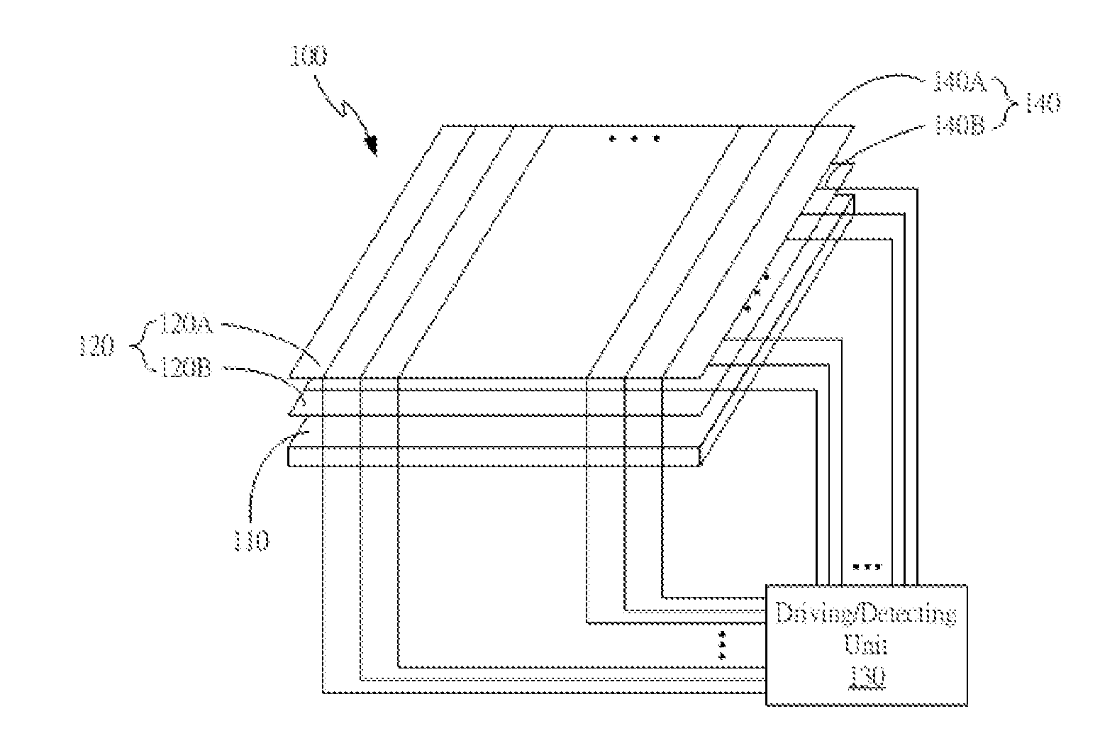
[0040]Accordingly, the present invention provides a device for location detection of a touch screen, which includes a detecting unit and a control unit. The detecting unit may be the driving / detecting unit shown in FIG. 2A for detecting changes in capacitances of a plurality of detecting locations on the touch screen, wherein each change in capacitances corresponds to a coordinate. The control unit may be the controller 160 shown in FIG. 2B for determining a profile corresponding to each external object based on the changes in capacitances of the detecting locations on the touch screen, and generating a coordinate data of each external object based on two values in the corresponding profile. Referring to FIG. 5, a method for location detection of a touch screen is proposed by the present invention. As shown in step 510, changes in capacitances of a plurality of detecting locations on a touch screen are detected, wherein each change in capacitances corresponds to a coordinate. Then, ...


PUM


Abstract

The changes of capacitances of a plurality of detecting locations on a touch screen are detected for determining a profile corresponding to each external object approaching or touching the touch screen. Then the location of each external object is generated separately by two or four values in the corresponding profile.

Description

CROSS REFERENCE TO RELATED APPLICATIONS[0001]This application claims priority under 35 U.S.C. 119 to Taiwan patent application, 101150822, filed on Dec. 28, 2012, the disclosure of which is incorporated herein by reference.BACKGROUND OF THE INVENTION[0002]1. Field of the Invention[0003]The present invention relates to a method and device for location detection, and more particularly, to a method and device for location detection with higher linearity.[0004]2. Description of the Prior Art[0005]A traditional capacitive touch screen typically includes an insulating surface layer, a first conductive layer, a dielectric layer, and a second conductive layer, wherein the first and second conductive layers have a plurality of first conductive strips and second conductive strips, respectively, and these conducting strips are made up by a plurality of conductive pads and connection wires connecting these conductive pads in series.[0006]The changes in capacitances of a plurality of detecting l...

Claims


Application Information

Patent Timeline
Patent Type & Authority Applications(United States)
IPC IPC(8): G06F3/044
CPCG06F3/044G06F3/0446G06F3/0445
Inventor YEH, SHANG-TAI
Owner EGALAX EMPIA TECH INC
Learn More