Arrangement for current limitation which is suitable for integration into a power supply serving network

a technology of current limitation and power supply, applied in the direction of superconducting magnets/coils, emergency protective arrangements for limiting excess voltage/current, magnetic bodies, etc., can solve the cost of manufacturing the bifilar arrangement of superconducting conductors equipped with supports, and achieve the effect of reducing the need for space, and reducing the cost of manufacturing

Inactive Publication Date: 2019-06-25
NEXANS
View PDF16 Cites 0 Cited by
  • Summary
  • Abstract
  • Description
  • Claims
  • Application Information

AI Technical Summary

Benefits of technology

[0012]This arrangement is connectable as a compact one-piece unit to a three phase alternating current, and in fact, over two electrical contact points for each phase conductor of the arrangement. The completion of the arrangement is relatively simple because the three phase conductors themselves, only in spiral form winding parallel to each other, must be arranged on each support. They can, on their ends, possibly be connected simply with further phase conductor arranged supports. At the same time, simple connecting conductors are sufficient, which are attached between the ends of the phase conductor of a support and the beginning of the phase conductor of a further support. The arrangement, independent of the number of phase conductor equipped supports built in only one container constructed as a cryostat, which with little effort, can be transported to the mounting area and there, compared to the known arrangement, can be set up with less space needed. Because all the necessary superconductive phase conductors can be brought together in only one cryostat for the arrangement, altogether less material is necessary for repairing the superconductive materials.

Problems solved by technology

The manufacture of the bifilar arranged superconductive conductor equipped with supports is costly.

Method used


Image

  • Arrangement for current limitation which is suitable for integration into a power supply serving network

Examples


Embodiment Construction

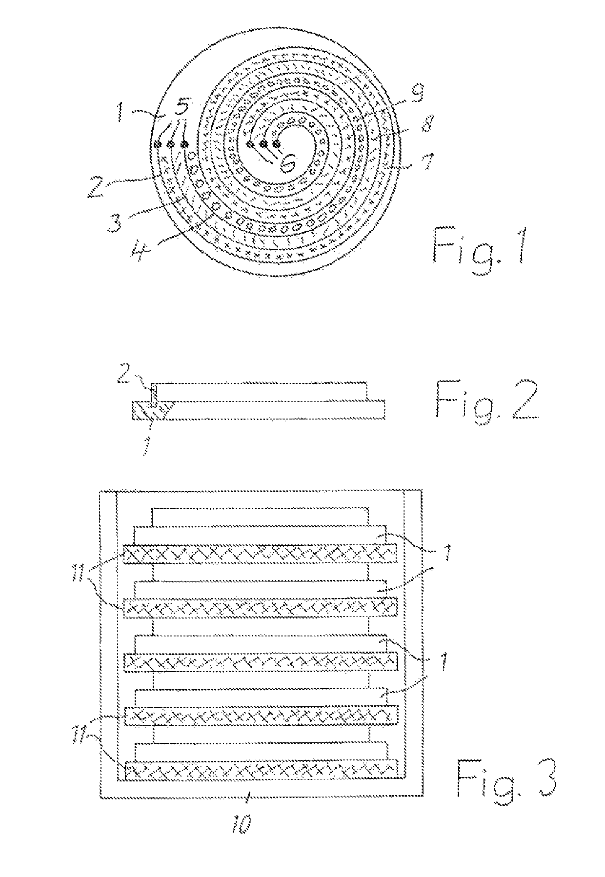
[0019]On a plate like support 1 composed of a mechanically stable synthetic material, such as for example reinforced fiberglass synthetic, are three superconductive phase conductors 2, 3 and 4 arranged and fastened on the same. The phase conductors 2, 3 and 4 run in a spiral form winding parallel to each other. They are arranged on the upper surface of the support 1 so that the upper surface of the support is generally covered. The ends of phase conductors 2, 3 and 4 are advantageously connected on the one side with contact element 5 and on the other side with contact element 6.

[0020]Between the windings of the phase conductors 2, 3 and 4 are arranged spacers 7, 8 and 9, which is stable to electrical voltage, composed of insulation material, corresponding with the illustrated embodiment, which through crosses and dashes as well as circles indicate the different parts. They are composed of for example, reinforced fiberglass synthetic. Each of the phase conductors 2, 3 and 4 can also ...


PUM

PropertyMeasurementUnit
superconductiveaaaaaaaaaa
electrical voltageaaaaaaaaaa
electrical insulationaaaaaaaaaa

Abstract

An arrangement for current limitation which is suitable for integration in a power supply serving network and which has a superconductive conductor, which is attached to at least one plate like support composed of insulation material. On the at least one support three separate from each other superconductive conductors in spiral form windings parallel to each other running to a separate connection is arranged on the phases of a three phase alternating current network. The support equipped with the phase conductors is built in to a container constructed as a cryostat.

Description

RELATED APPLICATION[0001]This application claims the benefit of priority from European Patent Application No. 15 306 183.3, filed on Jul. 21, 2015, the entirety of which is incorporated by reference.BACKGROUND[0002]Field of the Invention[0003]The invention relates to an arrangement for current limitation which is suitable for integration into a power supply serving network and which has a superconductive conductor, which is attached to at least one plate like support composed of insulation material.[0004]Description of Related Art[0005]One such arrangement is known and is described in for example, BP 0 503 448 A2, DE 10 2004 048 646 B4 and DE 10 2006 029 722 B3. It serves to prevent short circuits in the power supply serving network. In addition, the properties of the superconductive materials will be utilized, which will be superconductive at sufficiently low temperatures and by exceeding a certain current strength, the critical current strength is transformed to the normal conduct...

Claims


Application Information

Patent Timeline
Patent Type & Authority Patents(United States)
IPC IPC(8): H01F6/06H01F6/04H01L39/16
CPCH01F6/04H01L39/16H01F6/06H10N60/30Y02E40/60H01B12/02H02H9/023H01B12/14H01B12/16
Inventor STEMMLE, MARKWEST, BEATE
Owner NEXANS
Why Eureka
Try Eureka