Top loading battery holder

a battery holder and top loading technology, applied in the field of top loading battery holder, can solve the problems of large space, complex and cumbersome fastening and/or covering system, and high production cost of loading battery holder, and achieve the effect of minimal space, convenient access, and convenient arrangemen

Active Publication Date: 2019-06-25
MEMORY PROTECTION DEVICES
View PDF15 Cites 0 Cited by
  • Summary
  • Abstract
  • Description
  • Claims
  • Application Information

AI Technical Summary

Benefits of technology

[0004]The present invention broadly is directed to a top loading battery holder that can be arranged in direct contact with a surface, including a circuit board, allowing for a battery to be easily arranged within the holder. The battery holder encompasses a minimal amount of space, requires very few components and is easy to access when necessary to install or replace a battery.
[0008]In an embodiment, the housing can include a plurality of sidewalls that extend at angles from each other and a plurality of flanges extending from the sidewalls for mounting of the housing to the circuit board. The housing can include seven sidewalls that extend at angles from each other to substantially surround the battery. The sidewalls can include a first end and a second end that includes a flange extending inwardly from a plurality of the sidewalls toward a center of the housing with a plurality of elastically deformable projections extending from the flange that are contactable with the battery arranged in the housing to aid in securing the battery within the housing.

Problems solved by technology

However, these battery holders typically require a substantial amount of space on a surface of a circuit board and, as is the case for side loading battery holders, require additional space for clearance to allow a battery to be installed and removed.
Additionally, many existing battery top loading holders require a plurality of complex and cumbersome fastening and / or covering systems to ensure a battery is secured within the holder and in contact with the circuit board.
As such, existing top loading battery holders are costly to produce, time consuming to assemble and can be difficult to access to remove and replace a battery when necessary due to the fastening and / or covering system used to secure the battery in the holder.

Method used


Image

  • Top loading battery holder
  • Top loading battery holder
  • Top loading battery holder

Examples


first embodiment

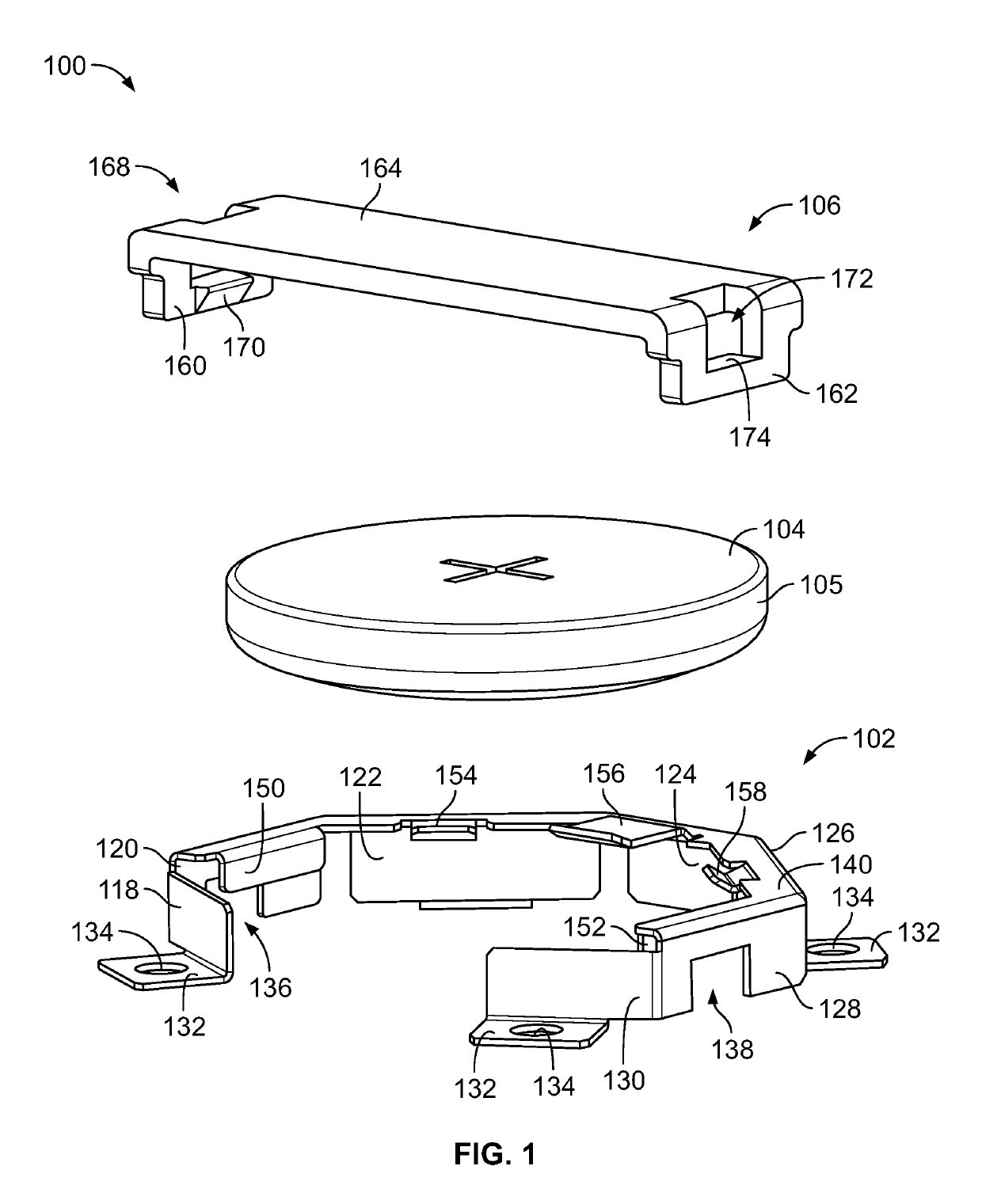
[0030]FIG. 1 illustrates a top loading battery holder that is designated hereinafter by reference numeral 100. The top loading battery holder 100 includes a housing 102 that is shaped to at least substantially surround a battery 104 (e.g., coin cell battery) and a retention element 106 that interacts with the housing 102 to aid in securing the battery 104 within the housing 102 by partially covering the battery 104. The housing 102, as will be described in more detail below, is fastenable to a surface (e.g., a circuit board) so that when the battery 104 is inserted into the housing 102, the housing 102 will be in direct contact with the surface.

[0031]The housing 102 includes a plurality of sidewalls that form a frame or cage to substantially surround the battery 104 when the battery 104 is arranged therein. As shown in FIG. 1, the housing 102, which includes a first sidewall 118, a second sidewall 120 extending at an angle from the first sidewall 118, a third sidewall 122 extending ...

second embodiment

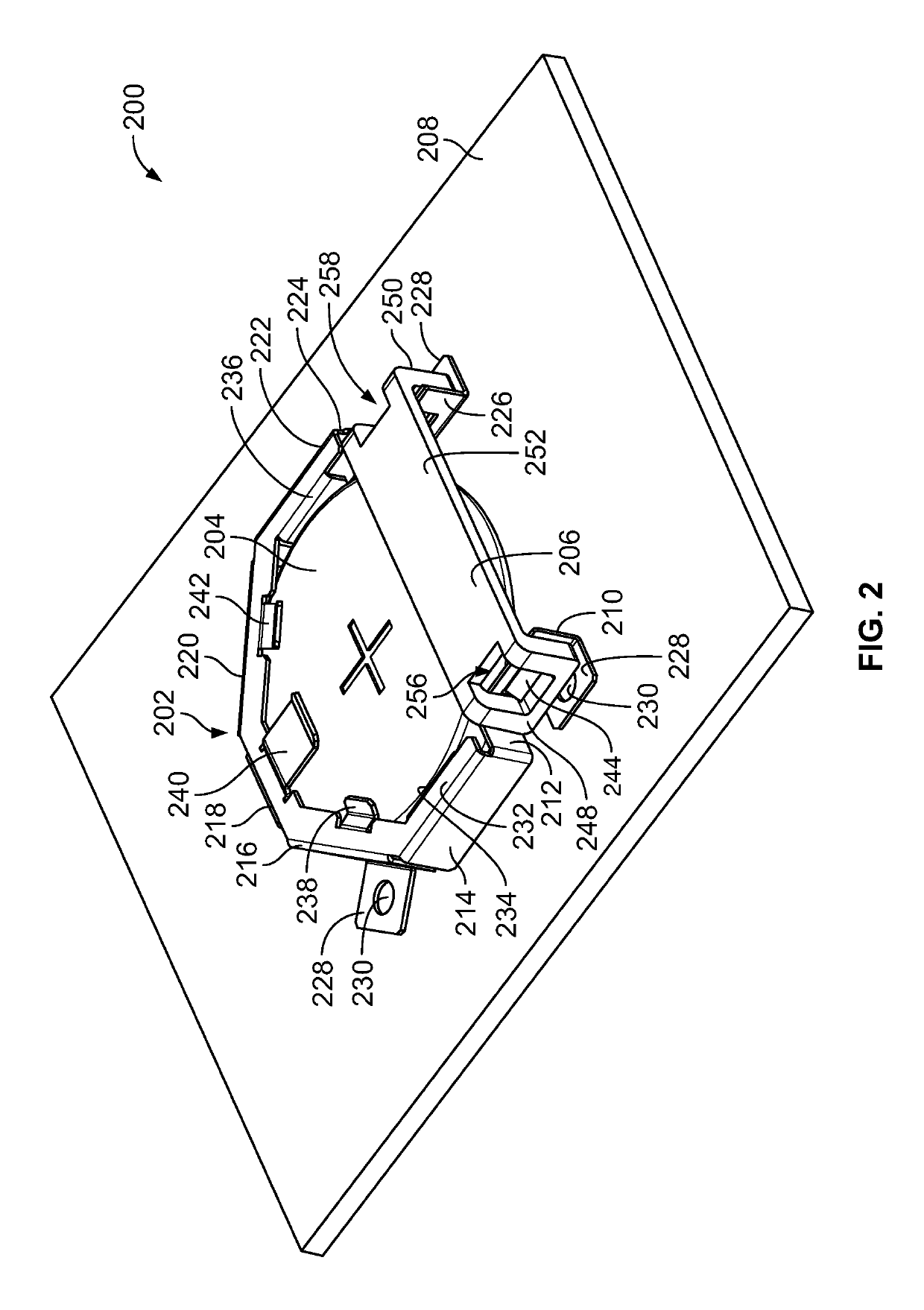
[0036]FIG. 2 illustrates a top loading battery holder that is designed hereinafter by reference numeral 200. The top loading battery holder 200 includes a housing or cage 202 that is mountable to a surface (e.g., circuit board) 208 and is shaped to at least substantially surround a battery 204 (e.g., coin cell battery) and a retention element 206 that interacts with the housing 202 and partially covers the battery 204 to aid in securing the battery 204 within the housing 202. As shown in FIG. 2, the battery holder 200 is mounted to a circuit board 208.

[0037]The housing or cage 202 comprises a plurality of sidewalls including a first sidewall 210, a second sidewall 212 extending substantially perpendicular from the first sidewall 210, a third sidewall 214 extending substantially perpendicular from the second sidewall 212, a fourth sidewall 216 extending at an angle from the third sidewall 214, a fifth sidewall 218 extending at an angle from the fourth sidewall 216, a sixth sidewall 2...

fifth embodiment

[0051]FIGS. 9-11 illustrate a top loading battery holder 500. The top loading battery holder 500 includes a housing 502 that is shaped to entirely surround a battery 504 (e.g., coin cell battery). The housing 502, as shown in FIG. 11 is fastenable to a surface (e.g., a circuit board) 506 so that when the battery 504 is inserted into the housing 502, the housing 502 will be in direct contact with the surface 506.

[0052]The housing 502 includes a plurality of sidewalls that form a frame or cage to entirely surround the battery 504 when the battery 504 is arranged therein. As shown in FIGS. 9-11, the housing 502 includes a first sidewall 508, a second sidewall 510 that extends at an angle from the first sidewall 508, a third sidewall 512 that extends at an angle from the second sidewall 510, a fourth sidewall 514 that extends at an angle from the third sidewall 512, a fifth sidewall 516 that extends at an angle from the fourth sidewall 514, a sixth sidewall 518 that extends at an angle ...


PUM

PropertyMeasurementUnit
positive conductiveaaaaaaaaaa
polarityaaaaaaaaaa
an angleaaaaaaaaaa

Abstract

A top loading battery holder that is arranged in direct contact with a surface (e.g., circuit board) to allow for a battery to be arranged directly within the holder and in electrical contact with the surface. The battery holder can include a housing that is configured to at least substantially surround a battery that is arranged therein and a plurality of a flanges and / or protrusions that are configured to extend inwardly from the housing to aid in securing the battery within the housing.

Description

FIELD OF THE INVENTION[0001]This invention relates generally to a battery holder and more specifically to a top loading battery holder that is positionable directly on a surface of an object (e.g., a printed circuit board) and that is configured to allow a battery to be received directly therein or removed therefrom.BACKGROUND OF THE INVENTION[0002]Devices that utilize a battery regularly require an apparatus to fix the battery in a desired position in order to maintain an electrical connection between the battery and the device. In many instances, the device includes a circuit board.[0003]Commonly, battery holders, including side loading battery holders and top loading battery holders, are connected to a circuit board to place a battery in electrical connection with the circuit board. However, these battery holders typically require a substantial amount of space on a surface of a circuit board and, as is the case for side loading battery holders, require additional space for cleara...

Claims


Application Information

Patent Timeline
Patent Type & Authority Patents(United States)
IPC IPC(8): H01M2/02H01M2/10H01M10/42H01M50/109H01M50/202H01M50/224H01M50/244H01M50/262H01M50/284
CPCH01M2/1022H01M2/02H01M10/425H01M2/1038H01M2/10Y02E60/10H01M50/216H01M50/224H01M50/284H01M50/202H01M50/109H01M50/262H01M50/244H05K1/181H05K2201/10037H05K2201/10325
Inventor BLAHA, THOMASENGELSTEIN, CHARLES
Owner MEMORY PROTECTION DEVICES
Why Eureka
Try Eureka