
Dynamic switching between edge nodes in autonomous network system

a network system and edge node technology, applied in the field of network traffic routing, can solve the problems of ineffective network performance improvement of edge nodes, undesirable frequent broadcasting, and inability to readily access information of one autonomous system that is needed for routing determination to another autonomous system, so as to improve the network performance of the autonomous system

Active Publication Date: 2019-06-25
ALGOBLU HLDG
View PDF31 Cites 1 Cited by
  • Summary
  • Abstract
  • Description
  • Claims
  • Application Information

AI Technical Summary

Benefits of technology

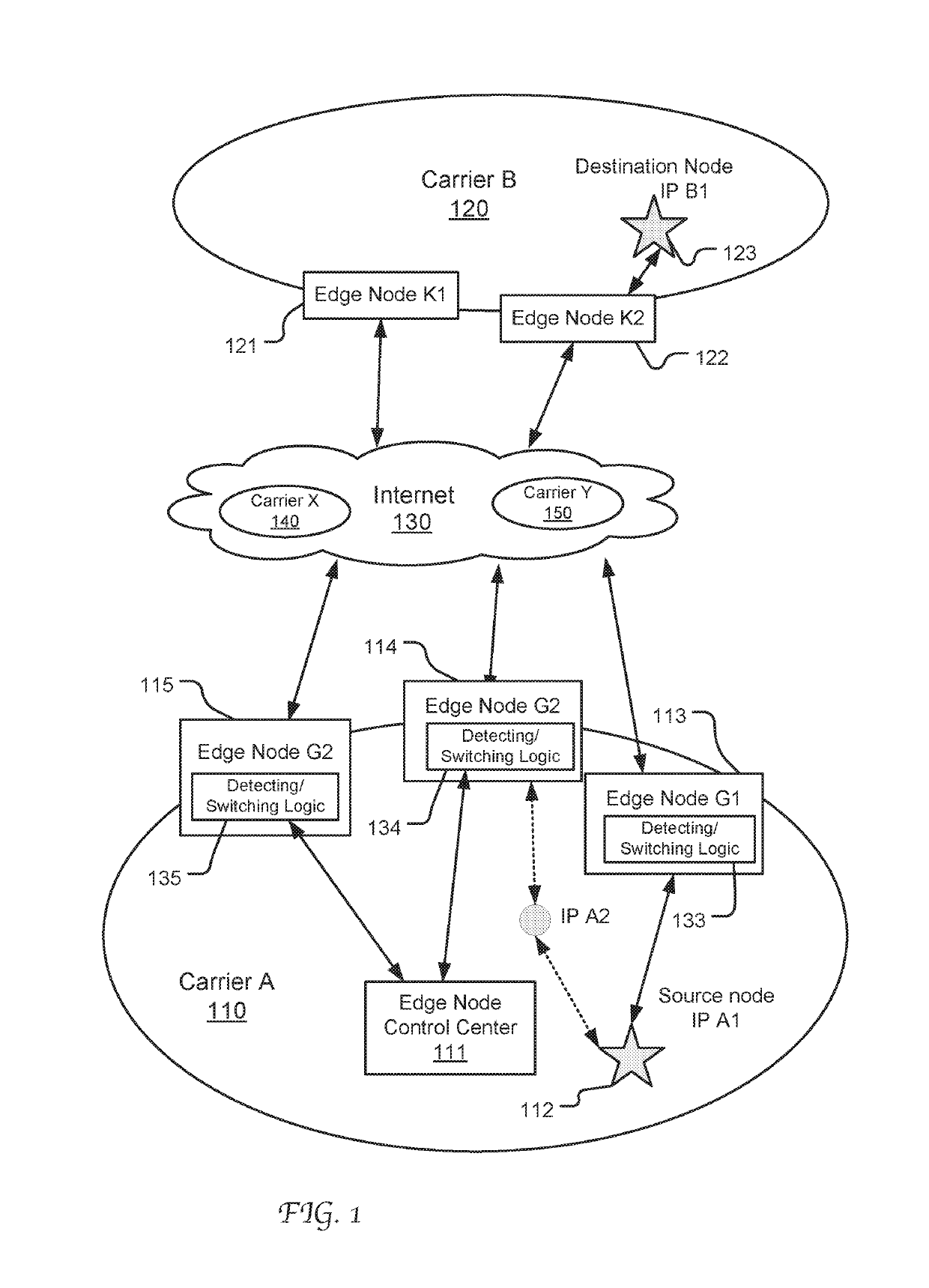
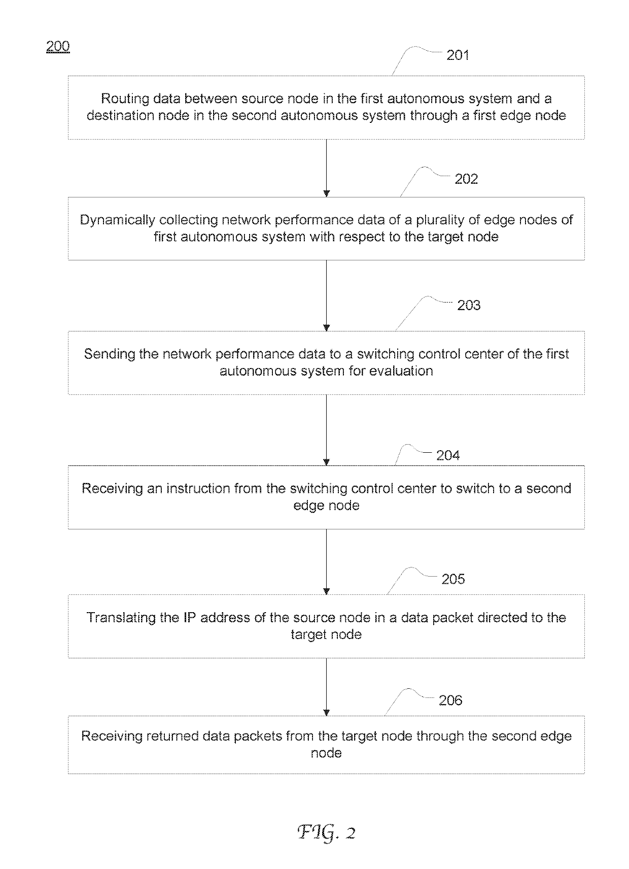
The present patent describes a mechanism for improving network performance in an autonomous system by dynamically allocating edge nodes based on real-time network performance. This approach offers flexibility in controlling traffic migration among the edge nodes and ensures quality of service by taking into account the current conditions and statuses of the related network elements and links. The edge node switching is enabled by network address translation which is transparent to the external autonomous systems and avoids potential adverse effects from conventional broadcasting, such as traffic congestion. The technical effects of this invention include improved network performance and flexibility in controlling traffic migration among the edge nodes.

Problems solved by technology

Usually, the information of one autonomous system that is needed for routing determination is not readily available to another autonomous system, including a reassignment of the egress edge nodes.
This makes the change of edge node ineffective in terms of network performance improvement.
Frequent broadcasting is undesirable as it contributes to network traffic congestion.
However, broadcasting the reassignment of the involved subnetwork to another edge node causes a substantial amount traffic that is unrelated to the particular external antonymous system or link to migrate to the selected edge node as well.
Inevitably, this further counteracts the overall effect in network performance improvement.

Method used


Image

  • Dynamic switching between edge nodes in autonomous network system
  • Dynamic switching between edge nodes in autonomous network system
  • Dynamic switching between edge nodes in autonomous network system

Examples


Embodiment Construction

[0021]Reference will now be made in detail to the preferred embodiments of the present invention, examples of which are illustrated in the accompanying drawings. While the invention will be described in conjunction with the preferred embodiments, it will be understood that they are not intended to limit the invention to these embodiments. On the contrary, the invention is intended to cover alternatives, modifications and equivalents, which may be included within the spirit and scope of the invention as defined by the appended claims. Furthermore, in the following detailed description of embodiments of the present invention, numerous specific details are set forth in order to provide a thorough understanding of the present invention. However, it will be recognized by one of ordinary skill in the art that the present invention may be practiced without these specific details. In other instances, well-known methods, procedures, components, and circuits have not been described in detail ...


PUM


Abstract

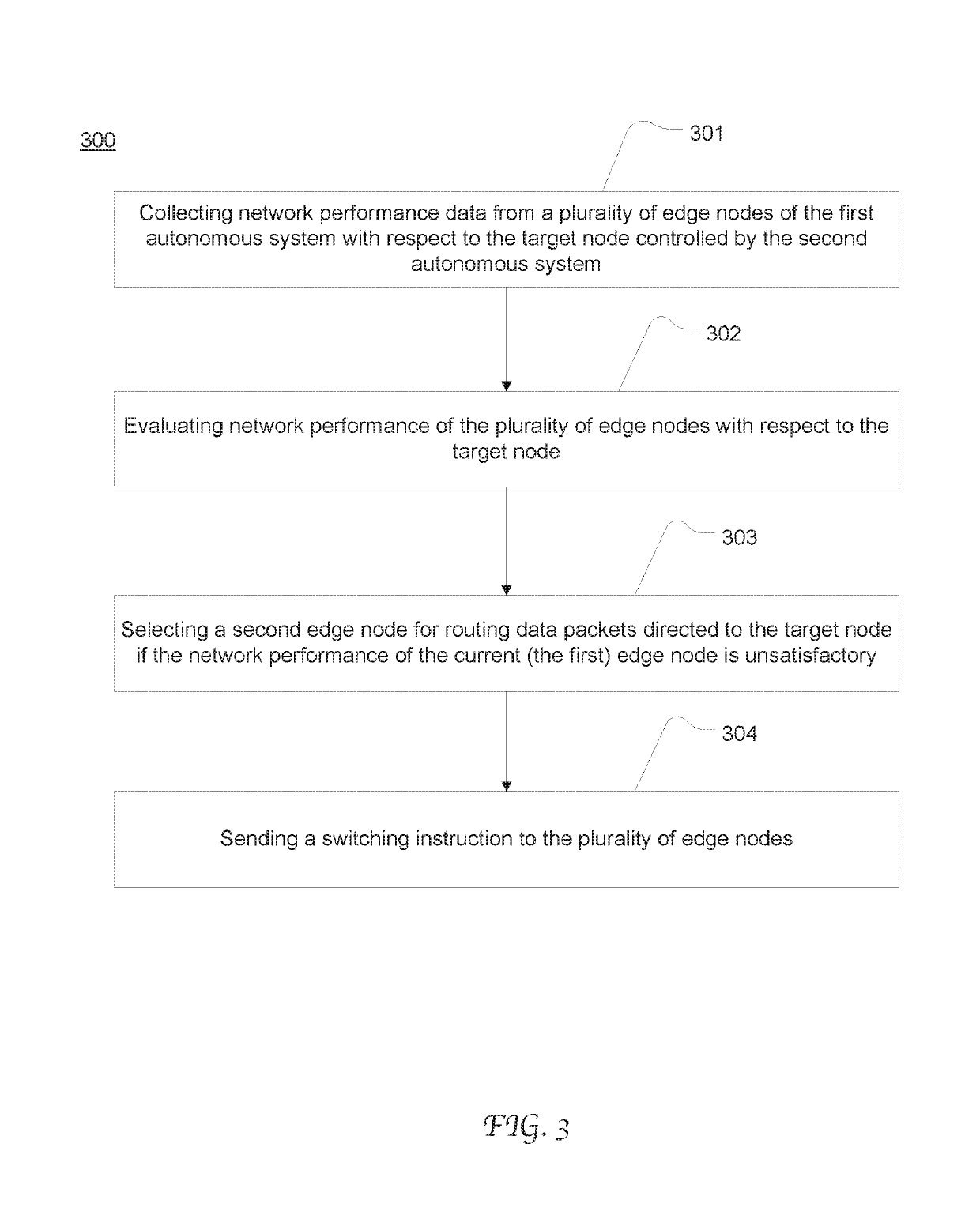
System and method of dynamically selecting an egress edge node for data transmission between different autonomous systems based on real-time route performance detection. With respect to a destination node located in a second autonomous system, a plurality of edge nodes in the first autonomous system each operate to detect route performance in real-time and send the detected information to a control center for evaluation. The evaluation results are compared and used to select an optimal edge node and an associated link for transporting data between the source node and the destination node. To switch from a first edge node to a second one, the IP address of the source node contained in the data packets are converted from an address assigned to the first edge node to an address assigned to the second edge node.

Description

CROSS REFERENCE[0001]This Patent Application claims priority to and benefit of Chinese Patent Application No. 201610423492.4, filed on Jun. 15, 2016, the content of which is herein incorporated by reference in entirety for all purposes.TECHNICAL FIELD[0002]The present disclosure relates generally to the field of network traffic routing, and, more specifically, to the field of routing across multiple autonomous systems.BACKGROUND OF THE INVENTION[0003]An autonomous system refers to a network or a collection of networks that are administrated by a single entity or organization, e.g., an Internet service provider (ISP). Typically, an autonomous system is a heterogeneous network having many subnetworks with combined routing logic and common routing policies. An autonomous system usually uses multiple ingress and egress edge nodes to interface with other autonomous system. Outbound data traffic of the autonomous system goes through a designated egress edge node to reach the destination n...

Claims


Application Information

Patent Timeline
Patent Type & Authority Patents(United States)
IPC IPC(8): H04L12/26H04W76/10H04L12/715H04L12/717H04L45/42H04L45/74
CPCH04L43/08H04L43/16H04W76/10H04L45/42H04L45/04H04L45/302H04L45/74H04L61/2503H04L41/12H04L43/10
Inventor LI, MING
Owner ALGOBLU HLDG
Learn More