Selective laser solidification apparatus and method

a laser solidification and laser technology, applied in the field of selective laser solidification apparatus and method, can solve the problems of increasing the cost of the apparatus by increasing the number of lasers, limiting the speed of the build set, and affecting the quality of the laser, so as to achieve a smaller radius and improve the quality of the spo

Active Publication Date: 2019-07-02
RENISHAW PLC
View PDF109 Cites 28 Cited by
  • Summary
  • Abstract
  • Description
  • Claims
  • Application Information

AI Technical Summary

Benefits of technology

[0009]By overlapping the scanning zones of the laser beams the same area can be built using different laser beams. In this way, there is flexibility in choosing which laser beam to use, allowing the processing unit to select a laser beam based on specified criteria. For example, the laser beam may be selected based on a total length of time each laser beam is used for solidifying areas in the powder layer. The laser beam may be selected to reduce or eliminate any difference in the total length of time each laser beam is used for solidifying areas in the powder layer. In this way, periods of non-utilisation of the laser beams are reduced or even eliminated. The selection of the laser beam may be a balance between competing factors, such as to reduce periods of non-utilisation of a laser beam balanced against solidifying areas in the powder layer that are upstream in the direction of gas flow, as described in our U.S. patent application No. 61 / 791,636.
[0015]The selection of the laser beam to use to scan an area of an object located within a region in which the scanning zones of the laser beams overlap may be carried out before the object is built. The processing unit may be arranged to determine a length of time each laser beam scans each powder layer based on a selection of the laser beams to use in scanning areas in each powder layer for a planned location of one or more objects to be built and to change the planned location of the one or more objects in the powder bed based on the determined lengths of time. For example, the object may be relocated to reduce or eliminate differences in the length of time the lasers scan areas in each layer.
[0024]In this way, a quality of the spot produced by the laser beam when scanning the point may be taken into account when selecting the laser beam to use to solidify the point in the powder layer. For example, favouring a laser beam that is at a smaller angle to the powder bed when scanning the point than another of the lasers may result in a better quality spot (more circular, smaller radius) being used when possible. Furthermore, crossing of the laser beams may be limited / avoided by favouring the laser beam that is at a smaller angle to the powder bed when scanning the point. It may be desirable to avoid crossing of the laser beams because of the thermal lensing effects produced by each laser beam and the effect such thermal lensing has on the other laser beam.

Problems solved by technology

However, the lasers may be underutilised during the build if, for any one of the lasers, the area to be solidified is larger in one of the quadrants than in the others.
Therefore, there is a limit on the speed of the build set by the time it takes the laser of the quadrant with the largest area to be solidified.
As the laser modules are a very expensive part of the apparatus, significantly increasing the cost of the apparatus by increasing the number of lasers but, at the same time, not using some of the lasers for large durations of the build is undesirable.

Method used


Image

  • Selective laser solidification apparatus and method
  • Selective laser solidification apparatus and method
  • Selective laser solidification apparatus and method

Examples


Embodiment Construction

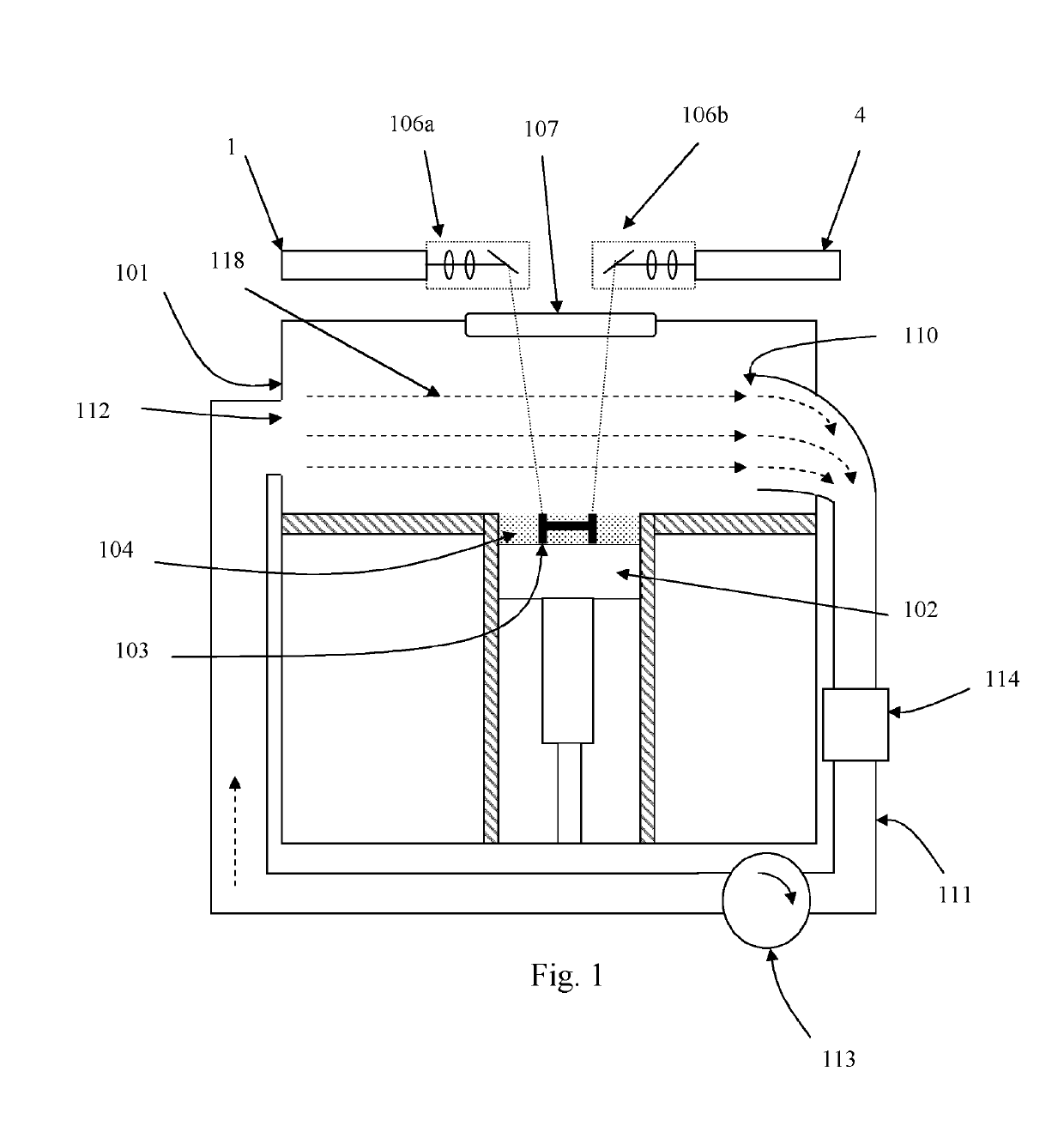
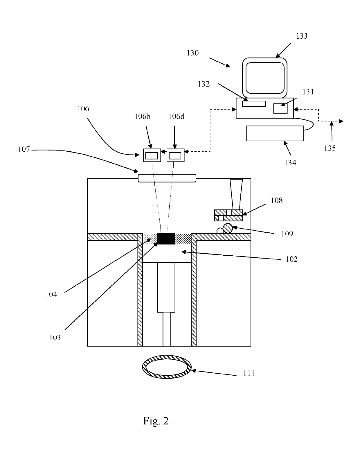
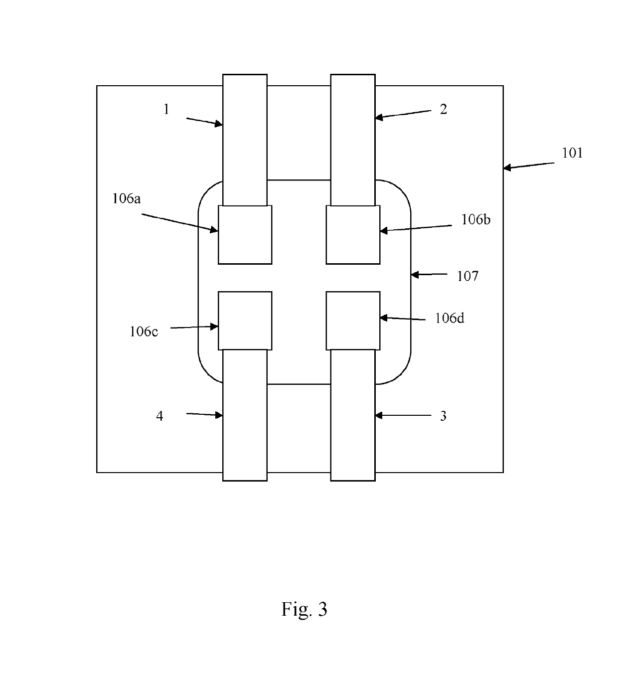
[0039]Referring to FIGS. 1 to 3, a laser solidification apparatus according to an embodiment of the invention comprises a build platform 102 for supporting an object 103 built by selective laser melting powder 104. The platform 102 can be lowered in the chamber 101 as successive layers of the object 103 are formed. Layers of powder 104 are formed as the object 103 is built by dispensing apparatus 108 and a wiper 109. For example, the dispensing apparatus 109 may be apparatus as described in WO2010 / 007396. Laser modules 1, 2, 3 and 4 each generate a laser beam for melting the powder 104, each laser beam directed as required by corresponding optical modules 106a to 106d under the control of a computer 130. The laser beams enter the build chamber via a window 107. Each laser beam can be independently steered to solidify separate areas of the powder bed 104. The range of locations to which each laser beam can be steered on the powder bed 104 defines a scanning zone, illustrated in FIG. ...


PUM

PropertyMeasurementUnit
areaaaaaaaaaaa
lengthaaaaaaaaaa
total lengthaaaaaaaaaa

Abstract

A selective laser solidification apparatus including; a powder bed onto which powder layers can be deposited, at least one laser module for generating a plurality of laser beams for solidifying the powder material deposited onto the powder bed, a laser scanner for individually steering each laser beam to solidify separate areas in each powder layer, and a processing unit. A scanning zone for each laser beam is defined by the locations on the powder bed to which the laser beam can be steered by the laser scanner. The laser scanner is arranged such that each scanning zone is less than the total area of powder bed and at least two of the scanning zones overlap. The processing unit is arranged for selecting, for at least one powder layers, which laser beam to use to scan an area of the powder layer located within a region wherein the scanning zones overlap.

Description

[0001]The present invention relates to selective laser solidification and, in particular, to a selective laser melting process and apparatus in which multiple laser beams are used to solidify the layers, separate areas of a layer solidified by different laser beams.BACKGROUND[0002]Additive manufacturing or rapid prototyping methods for producing objects comprise layer-by-layer solidification of a material, such as a metal powder material, using a laser beam. A powder layer is deposited on a powder bed in a build chamber and a laser beam is scanned across portions of the powder layer that correspond to a cross-section of the object being constructed. The laser beam melts or sinters the powder to form a solidified layer. After selective solidification of a layer, the powder bed is lowered by a thickness of the newly solidified layer and a further layer of powder is spread over the surface and solidified, as required. In a single build, more than one object can be built, the objects sp...

Claims


Application Information

Patent Timeline
Patent Type & Authority Patents(United States)
IPC IPC(8): B23K26/342B23K26/06B23K26/082B22F3/105B29C64/153B29C64/386B23K26/144B33Y50/02B33Y30/00B33Y40/00B33Y10/00
CPCB23K26/342B22F3/1055B23K26/0604B23K26/082B23K26/144B29C64/153B29C64/386Y02P10/295B22F2003/1056B33Y10/00B33Y30/00B33Y40/00B33Y50/02B29C64/393Y02P10/25B22F12/44B22F10/28B22F10/366B22F10/322B22F12/49B22F12/70B22F10/77B22F12/45
Inventor FERRAR, BEN IANBROWN, CERI
Owner RENISHAW PLC
Why Eureka
Try Eureka