Substrate transfer teaching method and substrate processing system

a substrate processing system and substrate technology, applied in the direction of conveyors, electrical devices, semiconductor devices, etc., can solve the problems of deviation from the accurate transfer position, interference with the transfer arm or the support pin, and difficulty in teaching the delivery position of the wafer in a vertical direction by the sensor, so as to achieve efficient teaching

Active Publication Date: 2019-07-02
TOKYO ELECTRON LTD
View PDF9 Cites 1 Cited by
  • Summary
  • Abstract
  • Description
  • Claims
  • Application Information

AI Technical Summary

Benefits of technology

[0010]In view of the above, the disclosure provides a technique for efficiently teaching a delivery position in a vertical direction in the case of delivering a substrate between an arm of a transfer unit and pins of a processing apparatus.

Problems solved by technology

When the transfer position of the transfer arm is not accurately aligned with the support position of the support pins, the wafer may interfere with the transfer arm or the support pins, or the wafer may not be delivered to the transfer arm or the support pins.
However, during the operation of the transfer unit, the transfer arm does not access the accurate transfer position due to various errors such as manufacturing errors of components of the transfer arm, installation errors of the respective components, assembly errors of the transfer unit, and the like, which results in deviation from the accurate transfer position.
Although a general apparatus has a sensor for sensing a horizontal position of a wafer, it is difficult to perform teaching of a delivery position of the wafer in a vertical direction by the sensor.
However, in the case of using the teaching jig, a teaching becomes complicated and a cost is increased.

Method used


Image

  • Substrate transfer teaching method and substrate processing system
  • Substrate transfer teaching method and substrate processing system
  • Substrate transfer teaching method and substrate processing system

Examples


first embodiment

2. First Embodiment of Teaching

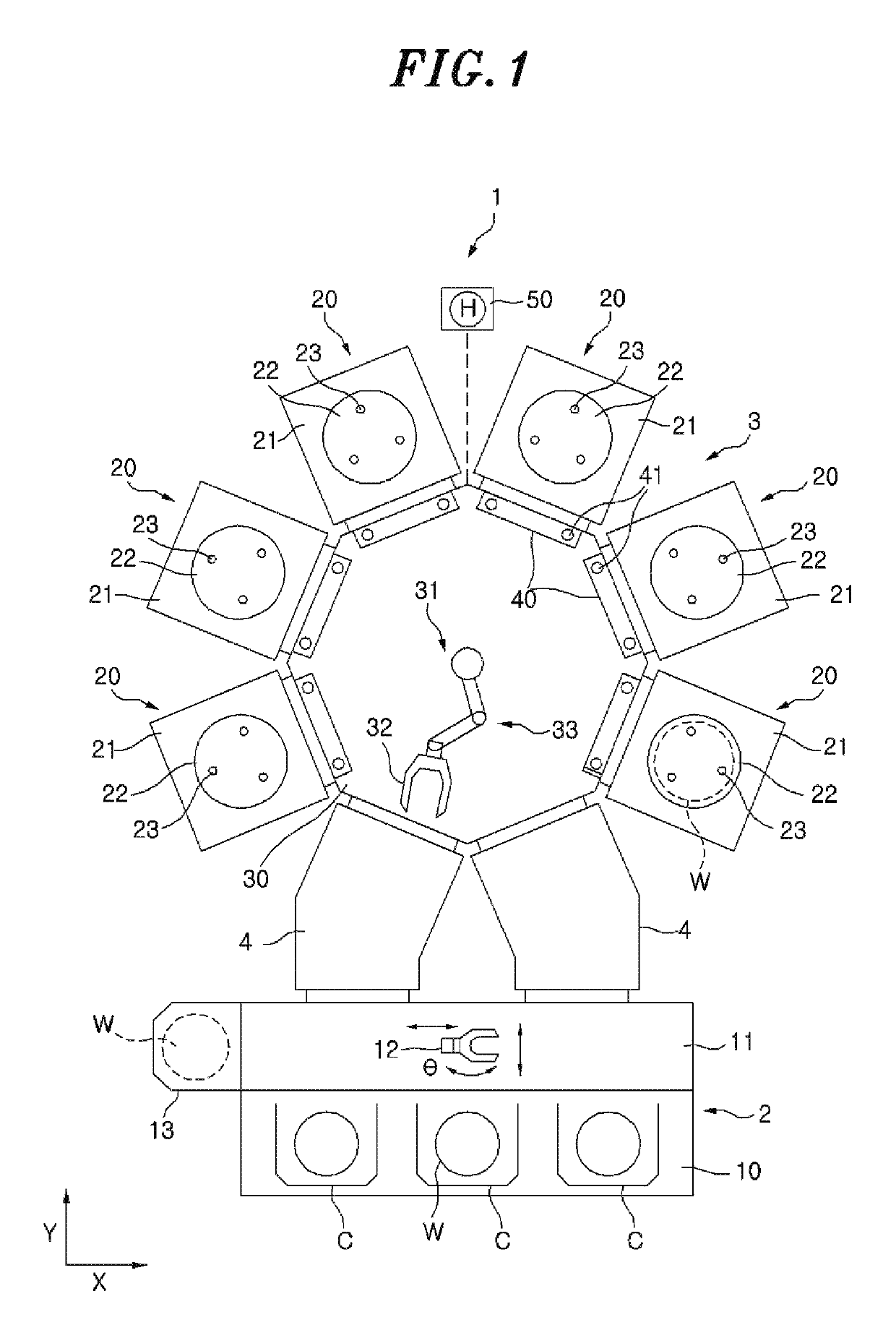
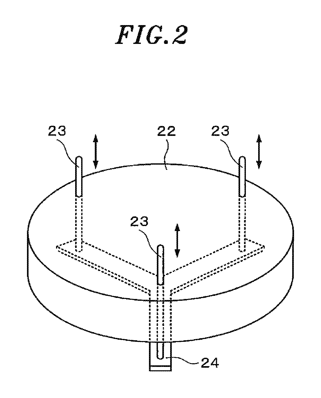
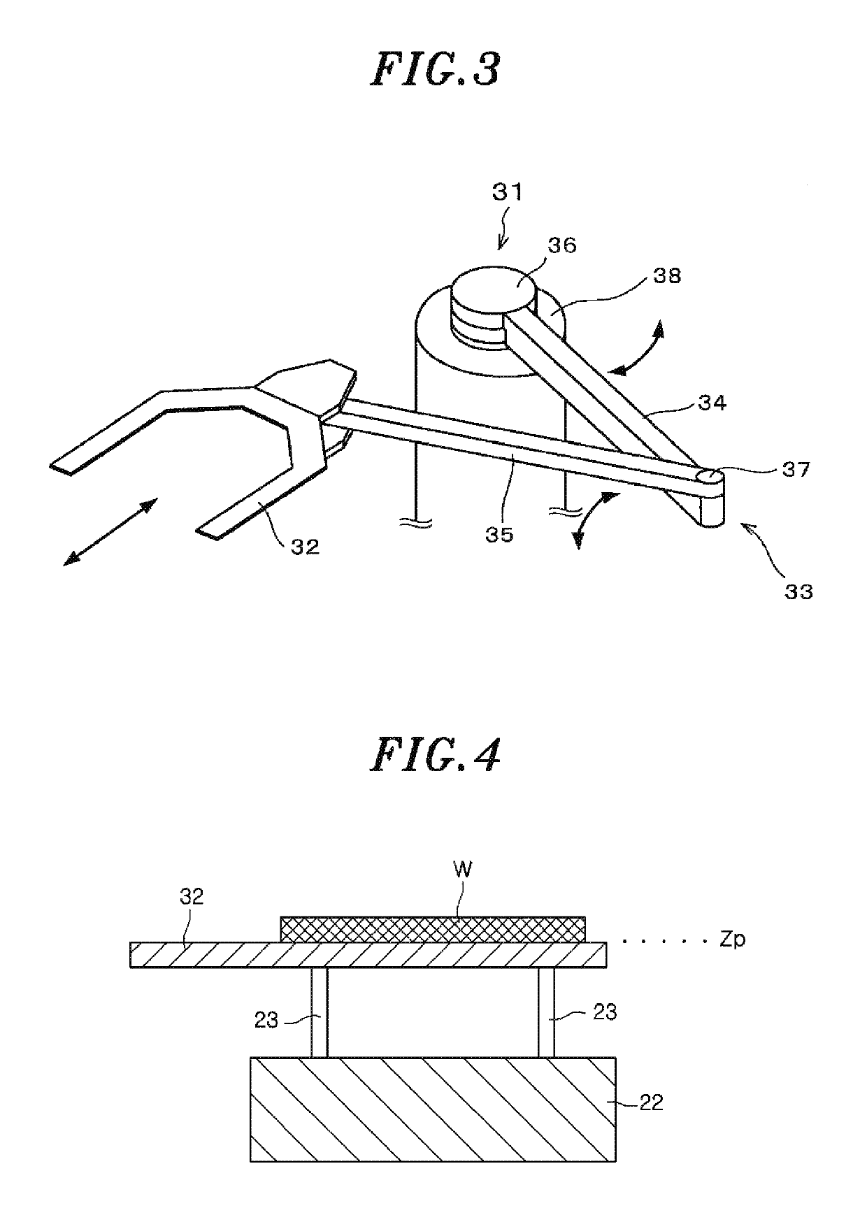
[0034]The following is description on the teaching of the delivery position of the wafer W which is performed by the substrate processing system 1 configured as described above. As shown in FIG. 4, a delivery position Zp of the wafer W is a position where a transfer position (top surface) of the transfer arm 32 and a support position (leading end portions) of the support pins 23 are on the same plane. The wafer W used for the teaching may be a product wafer or a dummy wafer (bare wafer).

[0035]First, a first embodiment of the teaching of the delivery position of the wafer W will be described. In the first embodiment, in order to perform the teaching, the transfer arm 32 is moved in a vertical direction in a state where the wafer W is supported by the support pins 23. Before the teaching is performed, a space that is enough for the transfer arm 32 to move in a vertical direction is ensured between a backside of the wafer W supported by the support pins 2...

second embodiment

3. Second Embodiment of Teaching

[0056]Next, a second embodiment of teaching of the delivery position of the wafer W will be described. In the second embodiment, when the teaching is performed, the transfer arm 32 is moved in a vertical direction in a state where the wafer W is held by the transfer arm 32. FIGS. 7A to 7F are views for explaining a teaching operation of the second embodiment, wherein FIGS. 7A to 7E are side views showing states of the transfer arm 32 and the support pins 23, and FIG. 7F schematically shows movement of the transfer arm 32 in the respective steps shown in FIGS. 7A to 7E.

[0057]First, as shown in FIG. 7A, the transfer arm 32 is moved in a horizontal direction and positioned above the mounting table 22 (step B1 in FIG. 7F). At this time, a height position of the top surface of the transfer arm 32 is a reference position Z1. Further, the horizontal position of the transfer arm 32 is a proper position at which the wafer W is held by the transfer arm 32.

[0058...

third embodiment

4. Third Embodiment of Teaching

[0066]Next, a third embodiment of teaching of the delivery position of the wafer W will be described. In the third embodiment, when the teaching is performed, the support pins 23 are moved in a vertical direction in a state where the wafer W is held by the transfer arm 32. FIGS. 8A to 8F are views for explaining the teaching operation of the third embodiment, wherein FIGS. 8A to 8E are side views showing state of the transfer arm 32 and the support pins 23, and FIG. 8F schematically shows movement of the transfer arm 32 (indicated by solid arrows) and movement of the support pins (indicated by dotted arrows) in the respective steps shown in FIGS. 8A to 8E.

[0067]First, as shown in FIG. 8A, in a state where the wafer W is held by the transfer arm 32, the transfer arm 32 is moved in a horizontal direction and positioned above the mounting table 22 (step C1 in FIG. 8F). At this time, the height position of the leading end portions of the support pins 23 is...


PUM


Abstract

A method includes a first step of vertically moving the arm or the pins from a reference position in one direction by a predetermined distance, a second step of moving the arm in a horizontal direction, a third step of vertically moving the arm or the pins moved in the one direction in the other direction by a distance equal to or greater than the predetermined distance, a fourth step of detecting a horizontal position of the substrate held by the arm with respect to the arm. The steps are repeated. Whenever the processes are performed, the reference position in the first step is shifted in the one direction by the predetermined distance, and a vertical position of the arm or the pins which is obtained when the horizontal position of the substrate detected in the fourth step is deviated from a preset position is taught as the delivery position.

Description

CROSS-REFERENCE TO RELATED APPLICATION[0001]This application claims priority to Japanese Patent Application No. 2016-016954 filed on Feb. 1, 2016, the entire contents of which are incorporated herein by reference.FIELD OF THE INVENTION[0002]The disclosure relates to a method for teaching a transfer position in a vertical direction in the case of transferring a substrate between an arm of a transfer unit and pins of a processing apparatus, and a substrate processing system for performing the teaching method.BACKGROUND OF THE INVENTION[0003]For example, in a process of manufacturing a semiconductor device, a liquid crystal display or the like, various processes such as film formation, etching, oxidation and the like are performed on a semiconductor substrate or a substrate for use in liquid crystal display (hereinafter, simply referred to as “wafer”) in separate processing apparatuses. When a wafer is loaded into and unloaded from a processing apparatus, a transfer unit having a trans...

Claims


Application Information

Patent Timeline
Patent Type & Authority Patents(United States)
IPC IPC(8): H01L21/687H01L21/67H01L21/677H01L21/68
CPCH01L21/68742H01L21/67259H01L21/67748H01L21/681Y10S901/03Y10S901/46H01L21/67011H01L21/677H01L21/68H01L2221/67H01L2221/683B65G47/904B65G49/061B65G2201/022H01L21/67098H01L21/67196H01L21/67242H01L21/67712H01L21/67715H01L21/67742
Inventor SAKAUE, HIROMITSU
Owner TOKYO ELECTRON LTD
Why Eureka
Try Eureka