

Medical holding arm having annular LED display means
- Summary
- Abstract
- Description
- Claims
- Application Information
AI Technical Summary
Benefits of technology
Problems solved by technology
Method used
Image

Examples
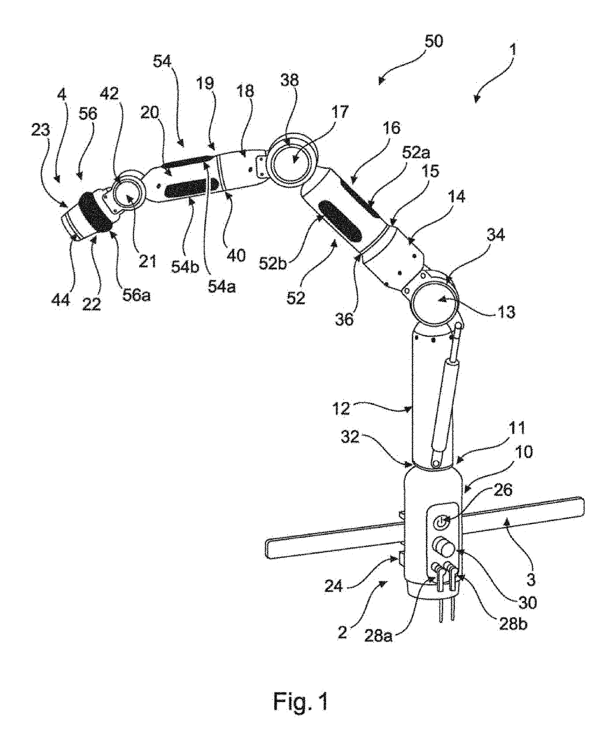
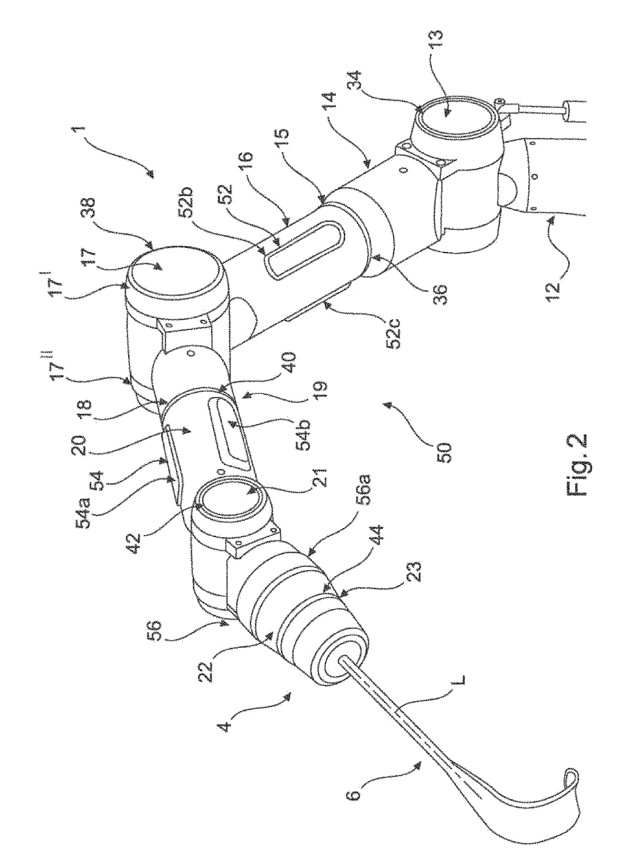
first embodiment
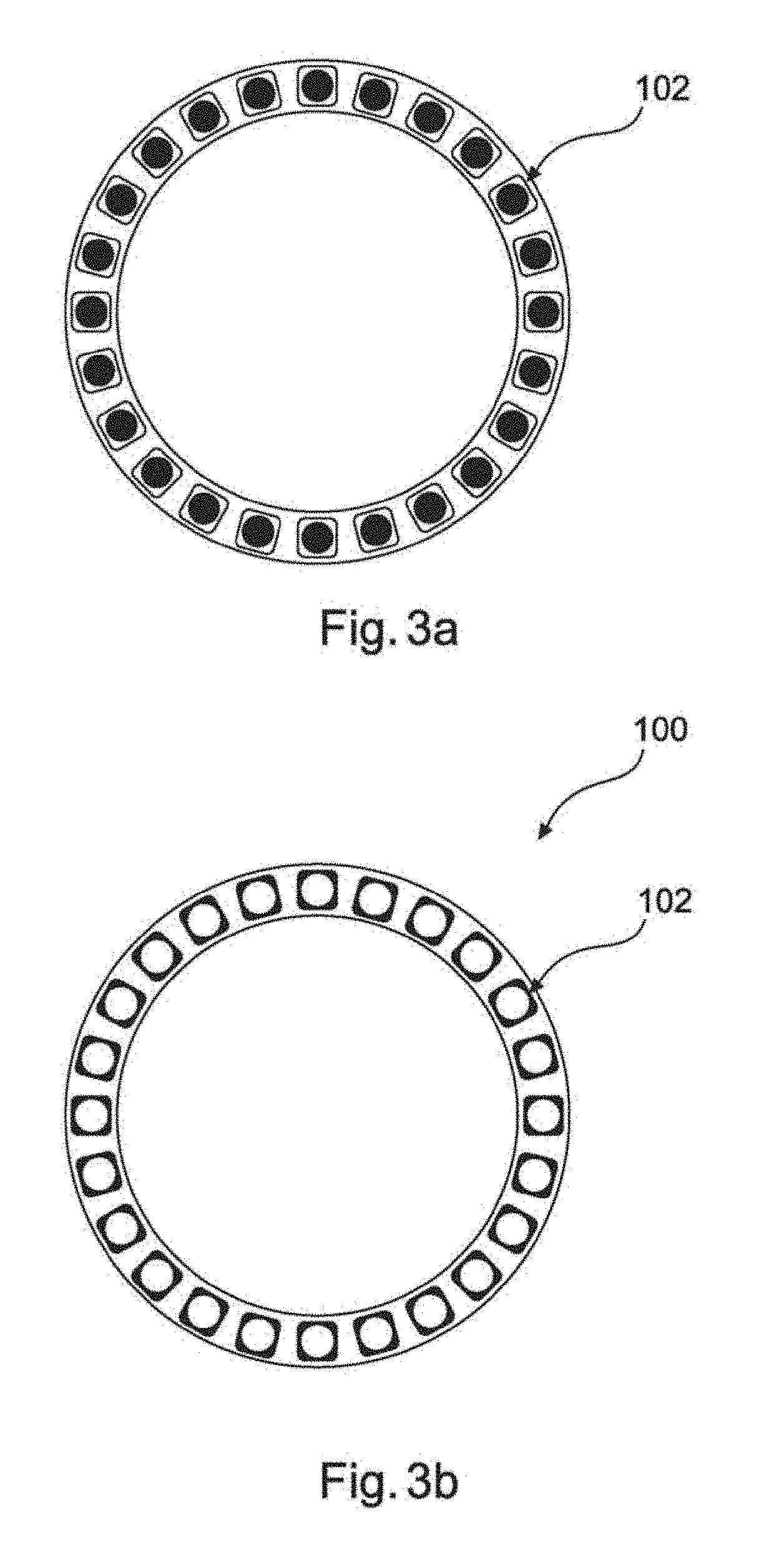
[0071]FIGS. 3a-7c show different embodiments of display units according to the invention, as well as their use to indicate a status of the holding apparatus and / or of an add-on device that is different from the releasing and / or locking of the respective joint. All the display units shown in FIGS. 3a-7c are designed as single rows. FIG. 3a shows a display unit 100 in a preferred embodiment of the invention. Display unit 100 is ring-shaped and has a plurality of annularly arranged LEDs 102 (in FIG. 3a, only one is marked with a reference sign). According to the embodiment shown in FIGS. 3a, 3b, LEDs 102 are oriented within the plane of the drawing in such a way that the display unit according to this embodiment can be used, for example, as a display unit 34, 38 or 42. Whereas display unit 100 is shown in a first state in FIG. 3a, the same display unit 100 is shown in in a second state in FIG. 3b. It should be understood that the two states can be an OFF state in FIG. 3a and an ON stat...
second embodiment
[0075]FIGS. 4a-4c and 5a-5c show a display unit 100 of the kind that is basically known from FIGS. 3a, 3b, in a FIGS. 4a-5c show display units which can not only switch between two or more different colours, but in which individual LEDs 102, 103, 104, 106 can take different colours (cf. FIGS. 4a-4c), or in which the luminous intensity is changed (cf. FIGS. 5a-5c). This is particularly advantageous when the holding apparatus is being positioned, and the operator is to be given feedback about such positioning. In one variant, it is preferred that a display unit 100, of the kind shown in FIGS. 5a-5c, lights up when a joint is moved, for example that display unit 38 lights up when joint 17 is moved. The luminous intensity can then be varied according to the speed of movement. In one such case, FIG. 5a shows a display unit 100 which indicates that there is no movement, FIG. 5b illustrates a movement performed at a medium speed, and FIG. 5c shows a movement performed at a high speed.
[007...
PUM
 Abstract
Description
Claims
Application Information