Painting device

a paint and nozzle technology, applied in the direction of electric static spraying apparatus, movable spraying apparatus, spray nozzle, etc., can solve the problems of reducing the application efficiency, wasting paint, and large paint application area on the workpiece, so as to improve the efficiency of painting the workpiece, improve the flexibility of the paint application range, and improve the effect of painting efficiency

Active Publication Date: 2019-07-09
HONDA MOTOR CO LTD
View PDF17 Cites 2 Cited by
  • Summary
  • Abstract
  • Description
  • Claims
  • Application Information

AI Technical Summary

Benefits of technology

[0003]Incidentally, in this type of painting device, due to the spread of the jetted shaping air, the paint discharged from the cup is easily scattered in the radially outward direction of the painting device, and the application area of the paint on the workpiece tends to be large. As a result, for example, in the case of a workpiece with a narrow application range, the paint is not concentrated in an intended range, which undesirably reduces application efficiency and results in waste of paint.
[0004]The present invention has been made to solve the above-described problem, and an object of the present invention is to provide a painting device that can improve the efficiency of application of paint to a workpiece by satisfactorily preventing the spread of the paint caused by shaping air with a simple configuration.

Problems solved by technology

Incidentally, in this type of painting device, due to the spread of the jetted shaping air, the paint discharged from the cup is easily scattered in the radially outward direction of the painting device, and the application area of the paint on the workpiece tends to be large.
As a result, for example, in the case of a workpiece with a narrow application range, the paint is not concentrated in an intended range, which undesirably reduces application efficiency and results in waste of paint.

Method used


Image

  • Painting device
  • Painting device
  • Painting device

Examples


Embodiment Construction

[0019]Hereinafter, a preferred embodiment of a painting device according to the present invention will be described in detail with reference to the attached drawings.

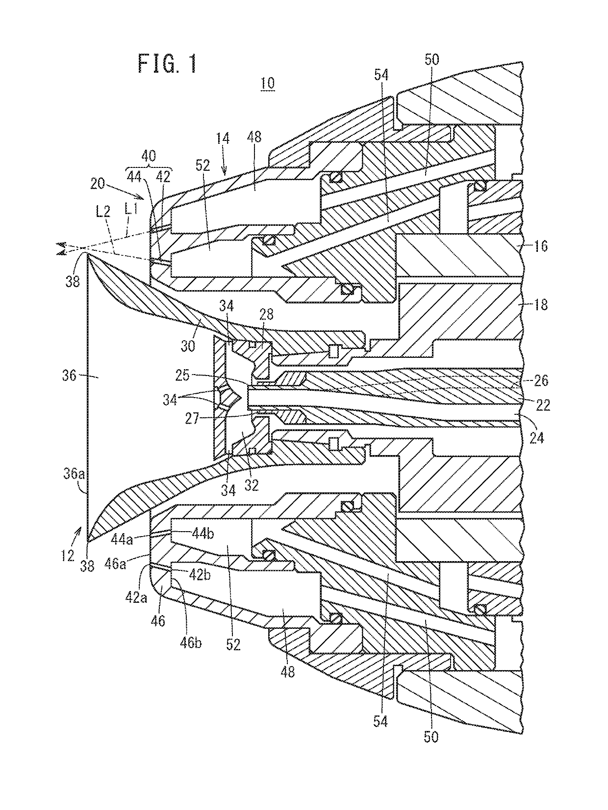
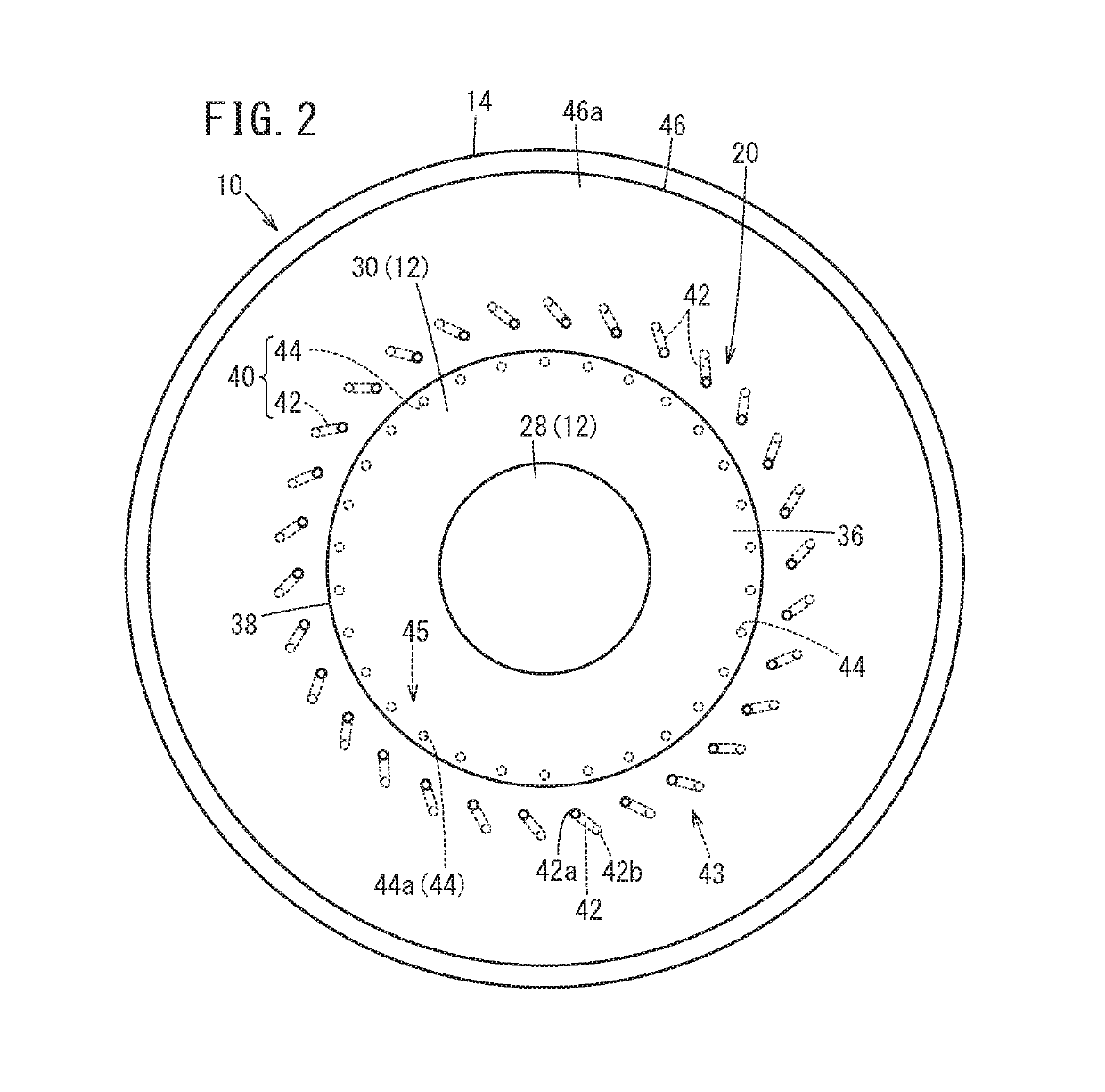
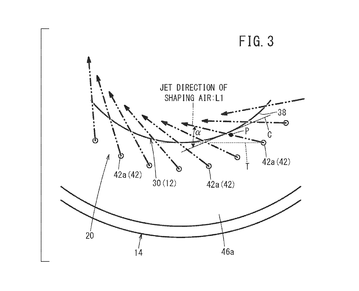
[0020]As depicted in FIG. 1, a painting device 10 according to an embodiment of the present invention is configured as a rotary atomization-type device including a bell-shaped cup 12 that discharges paint and a housing 14 that rotatably holds the cup 12. This painting device 10 applies paint to a workpiece (not shown), which is an object to be coated, by causing the paint to fly off radially outwardly by a centrifugal force which is generated at the time of rotation of the cup 12, and spraying the paint in a distal-end direction by shaping air jetted from the housing 14.

[0021]Specifically, the painting device 10 includes the above-described housing 14, an air motor 16 provided in the housing 14, a shaft 18 that is rotated by the air motor 16, the above-described cup 12 provided at a distal end of the shaft 18, and an ai...


PUM


Abstract

A painting device is provided with: a bell-shaped cup for discharging paint; a housing for holding the cup so as to be freely rotatable; and first tip openings disposed on the outside in the radial direction on the base end side of the tip side outer peripheral edge of the cup and throwing paint onto a workpiece by spraying shaping air in the direction of the tip. When a tangent line that is tangent to the tip side outer peripheral edge of the cup from a first tip opening is drawn in a front view of the painting device, the first tip opening sprays shaping air at an inclination more to the inside in the radial direction of the cup than the tangent line.

Description

TECHNICAL FIELD[0001]The present invention relates to a painting device that applies paint to a workpiece by spraying the paint by jetting out shaping air.BACKGROUND ART[0002]When a workpiece such as a body of an automobile is painted, a painting device (a rotary atomization painting device) as disclosed in Japanese Patent No. 2600390, for example, is used. By rotating a bell-shaped cup to thereby discharge paint, and jetting shaping air toward the distal-end-side outer peripheral edge of the cup, this painting device atomizes the discharged paint and applies the paint to a workpiece. Moreover, the jet direction of the shaping air of the painting device is directed along a tangent to the outer peripheral edge of the cup when viewed in a front view (see FIG. 2 of Japanese Patent No. 2600390).SUMMARY OF INVENTION[0003]Incidentally, in this type of painting device, due to the spread of the jetted shaping air, the paint discharged from the cup is easily scattered in the radially outward...

Claims


Application Information

Patent Timeline
Patent Type & Authority Patents(United States)
IPC IPC(8): B05B3/10B05B1/12B05B12/18B05B1/02B05B7/12B05B5/04
CPCB05B3/1014B05B1/02B05B1/12B05B3/10B05B5/0426B05B7/1272B05B12/18B05B5/04B05B5/0407B05B15/55
Inventor ITO, YUICHIOGASAWARA, SHINSHOJI, MASAAKI
Owner HONDA MOTOR CO LTD
Why Eureka
Try Eureka