
System and method to regulate primary side current using an event driven architecture in LED circuit

an event-driven architecture and led circuit technology, applied in the direction of lighting apparatus, electroluminescent light sources, light sources, etc., can solve the problems of increasing the correction frequency susceptible to high frequency errors, galvanically isolated secondary side current consumption information, etc., to speed up the loop response and speed up the effect of error correction

Active Publication Date: 2019-07-09
GLOBALFOUNDRIES U S INC
View PDF21 Cites 0 Cited by
  • Summary
  • Abstract
  • Description
  • Claims
  • Application Information

AI Technical Summary

Benefits of technology

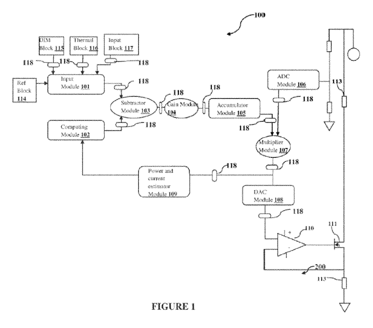
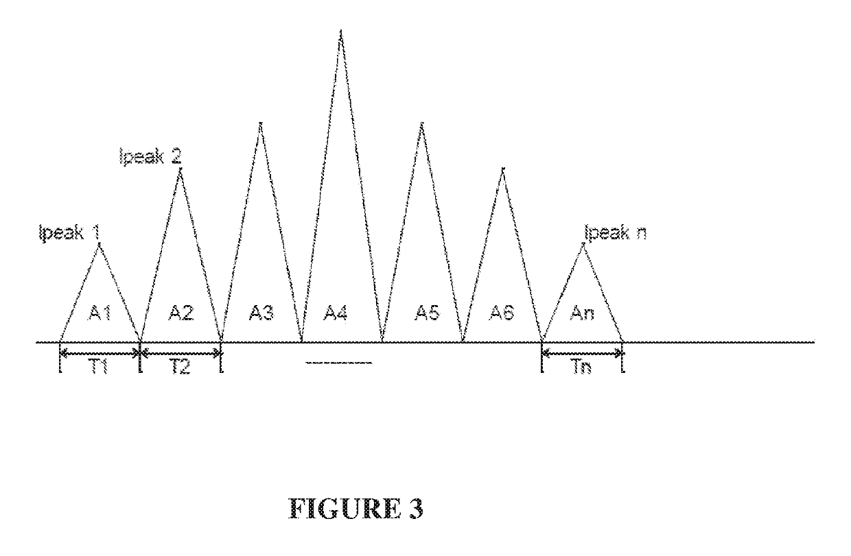
[0008]The present invention overcomes the drawbacks in the prior art and provides a system and method to regulate primary side current using an event driven architecture in LED circuit. The system comprises of an input module, a computing module, a subtractor module, a gain module, an accumulator module, an analog to digital module, a multiplier module, a digital to analog module, a Pulse Width Modulation (PWM) module, the power and current estimator module and a control module. The input module allows the user (s) to enter the desired reference voltage as per the requirement through a reference block. The computing module is configured to compute the average half cycle power or current from an input supply line cycle to generate the average feedback half cycle Peak Regulation Voltage (PRV) using an average filter. The subtractor module is configured to receive the desired reference voltage and the average feedback half cycle PRV or current from the input module and computing module. In the preferred embodiment, the received desired reference voltage and average feedback half cycle PRV or current is calculated by calculating the difference therein to produce an error signal using a subtractor. The gain module receives the difference error signal from the subtractor module and boost up the loop response and speed of error correction in the error signal by adding the gain signal. The accumulator module is configured to accumulate the error signal from the gain module and determine the level of effective reference set point signal to ensure the average feedback half cycle PRV equaling to the desired reference voltage using an accumulator. The Analog to Digital Converter (ADC) module is configured to regulate and convert the primary peak voltage to the digital signal to realize the wave shaping using an Analog to Digital Converter (ADC). The multiplier module multiplies the output of the analog to digital module and the accumulator module using a multiplier. The multiplier module contains information of the primary peak voltage and level of error signal. The Digital to Analog converter (DAC) module receives and converts the digital signal from the multiplier module to the analog signal using a Digital to Analog Converter (DAC). The DAC establishes the desired set voltage by regulating the primary peak voltage of the analog signal. The control module is configured to control the secondary side LED currents by regulating the primary peak voltage using a switch. The controlled secondary side currents are allowed to flow through a sense resistor to generate a voltage, wherein the generated voltage is in form of saw tooth waveform. The saw tooth waveform enables the user (s) to determine and calculate the turn ON time and turn OFF time of the switch to achieve regulation of secondary side currents by controlling the primary side currents.
[0013]In the preferred embodiment, the system further provides an offset error correction that may be added to the control loop to account for transformer ratio errors, inductor zero current errors and non linearity errors to improve the secondary side currents by controlling the primary side currents.
[0016]In the preferred embodiment of the invention, the method further resets filter average currents when there is interruption using a firmware.
[0017]The present invention provides a system and method which is simple, time saving, resource efficient, and cost effective. The invention may be used in variety of applications as indicator lamps and in different types of lighting environments which uses LED's.

Problems solved by technology

However, in the claimed systems, the secondary side current consumption information is galvanically isolated.
The use of an opto-coupler is an expensive approach and provides a weak link in the system to achieve accurate primary side regulation (PSR) in LED applications.
The increase in correction frequency susceptible to high frequency errors or noises and needs adequate filtering in LED applications.

Method used


Image

  • System and method to regulate primary side current using an event driven architecture in LED circuit
  • System and method to regulate primary side current using an event driven architecture in LED circuit
  • System and method to regulate primary side current using an event driven architecture in LED circuit

Examples


Embodiment Construction

[0027]Reference will now be made in detail to the description of the present subject matter, one or more examples of which are shown in figures. Each embodiment is provided to explain the subject matter and not a limitation. These embodiments are described in sufficient detail to enable a person skilled in the art to practice the invention, and it is to be understood that other embodiments may be utilized and that logical, physical, and other changes may be made within the scope of the embodiments. The following detailed description is, therefore, not be taken as limiting the scope of the invention, but instead the invention is to be defined by the appended claims.

[0028]The present invention discloses a system and method to regulate primary side current using an event driven architecture in LED circuit. The system (100) performs a primary side regulation (PSR) of isolated or non-isolated LED driver topology such as fly back system. The primary side peak voltage or current is regulat...


PUM


Abstract

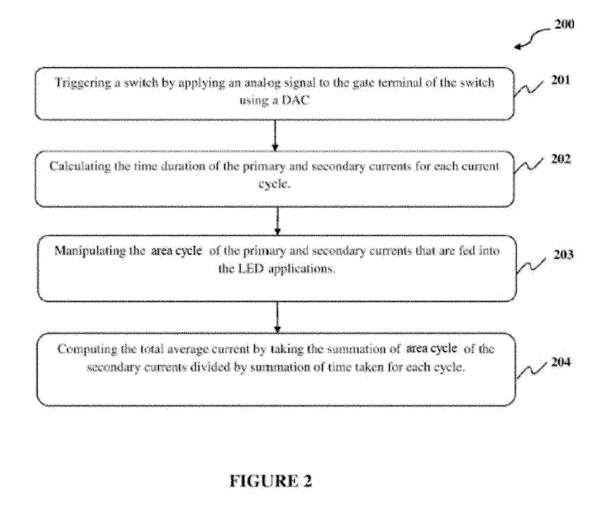
The present invention discloses system and method to regulate primary side current using an event driven architecture in LED circuit. The system (100) performs a primary side regulation (PSR) of isolated or non-isolated LED driver topology such as fly back system. The primary side peak voltage or current is regulated to achieve desired secondary side currents without the need of additional external components. The architecture combines firmware and hardware to realize PSR. The method (200) effectively combines input wave shaping (Active PFC), dimming and PSR to achieve accurate secondary side currents. The method (200) corrects the Peak Regulation Voltage or current (PRV) of primary loop to meet desired half cycle reference voltage or current, which in turn achieves the desired secondary loop current in LED circuit.

Description

TECHNICAL FIELD OF THE INVENTION[0001]The present invention relates to a system to achieve accurate primary side regulation (PSR), Power Factor Correction (PFC), dimming functionality without the need of external components. More particularly, the present invention relates to a method that corrects the PRV or current of primary loop to meet desired half cycle reference voltage or current, which in turn achieves the desired secondary loop currents in LED circuit.BACKGROUND OF THE INVENTION[0002]LEDs are current-driven devices. LEDs are used in a various kinds of electronic applications such as architectural lighting, automotive head and tail lights, backlights for liquid crystal display devices including personal computers and high definition TVs, flashlights, etc. A LED driver circuit generally requires a constant direct current (DC), which is fed to a LED load. The LEDs have significant advantages such as high efficiency, good directionality, color stability, high reliability, long...

Claims


Application Information

Patent Timeline
Patent Type & Authority Patents(United States)
IPC IPC(8): H05B37/02H05B33/08H05B44/00
CPCH05B33/0851H05B33/0818H05B33/0845H05B33/0815H05B45/10H05B45/3725H05B45/385H05B45/375
Inventor KHARE, ABHISEKSAMANTHA, SOMNATHBHAGWAT, KRISHNADASBOSE, SUMON KBHAGWAT, HRISHIKESHSWAMINATHAN, RAJESHKARPUR, RAMESH G
Owner GLOBALFOUNDRIES U S INC
Learn More