Double-sided circular cutting insert and indexable rotary cutting tool

a cutting tool and indexable technology, applied in the field of cutting inserts, can solve the problems of abnormal wear of cutting edges, deterioration of the machining accuracy of the machined surface of the workpiece, and easy displacement of cutting inserts, so as to improve the surface accuracy of the machined surface, and prevent or suppress vibrations.

Active Publication Date: 2019-07-16
HITACHI TOOL ENG LTD
View PDF36 Cites 4 Cited by
  • Summary
  • Abstract
  • Description
  • Claims
  • Application Information

AI Technical Summary

Benefits of technology

[0093]In the present invention, the first restraining wall and the second restraining wall are provided on the insert mounting seat of the tool main body of the indexable rotary cutting tool, a stage is provided at a position of the first restraining wall separated from the seating surface in a direction perpendicular to the seating surface, and the planar restraining wall surface and the antirotation wall surface are provided at the position at which the stage is provided. Similarly, the stage is provided at a position of the second restraining wall separated from the seating surface in the direction perpendicular to the seating surface, and the antivibration wall surface and the planar restraining wall surface are provided at the position at which the stage is provided. Meanwhile, in the circular cutting insert, the plurality of antivibration restraining faces, planar restraining faces, and antirotation surfaces (corners) are provided in each of the upper side surface and the lower side surface of the side surface. In addition, when the circular cutting insert is attached to the insert mounting seat, one of the antivibration restraining faces of the circular cutting insert comes into surface contact with and engages with the antivibration wall surface of the second restraining wall. Accordingly, the present invention can have the following effects.
[0094](1) When a cutting operation of a workpiece is performed using the indexable rotary cutting tool, in cutting forces applied to the cutting edge of the circular cutting insert, a component force in a circumferential tangential direction of a rotation trajectory of the cutting edge of the cutting tool is transmitted to the antivibration restraining faces of the circular cutting insert and strongly presses the antivibration restraining faces to the antivibration wall surface of the insert mounting seat. According to this pressing action, the antivibration wall surface of the tool main body receives the component force of the cutting forces, and thus, occurrence of vibrations is prevented or suppressed while a restraining force generated by the surface-contact and engagement between the antivibration wall surface and one of the antivibration restraining faces of the circular cutting insert is maintained. Therefore, it is possible to provide the circular cutting insert capable of preventing or suppressing occurrence of vibrations and the indexable rotary cutting tool to which the cutting insert is attached.
[0095](2) When an indexing operation of attaching the circular cutting insert to the insert mounting seat is performed, the planar restraining wall surface of the first restraining wall engages with the planar restraining face formed on the lower side surface of the side surface of the circular cutting insert, and the planar restraining wall surface of the second restraining wall engages with the planar restraining face formed on the upper side surface of the side surface of the circular cutting insert. Accordingly, it is possible to attach the circular cutting insert to the insert mounting seat without erroneous operations.
[0096]Moreover, the recessed portion of the antirotation wall surface provided on the first restraining wall engages with the corner of the side surface of the circular cutting insert, and thus, it is possible to prevent the circular cutting insert from rotating during the cutting operation.
[0097](3) According to the above (1) and (2), in the present invention, in the cutting operation using the indexable rotary cutting tool to which the double-sided circular cutting insert is attached, it is possible to improve surface accuracy of a machined surface of a workpiece and it is possible to remarkably improve a tool life.

Problems solved by technology

Even when the circular cutting insert is firmly fixed to the insert mounting seat, the cutting insert is easily displaced by a cutting force loaded to the cutting insert during a cutting operation of a workpiece.
If the circular cutting insert fixed to the insert mounting seat is rotated by the turning force (rotational moment) and the fixed position thereof is slightly shifted, machining accuracy of a machined surface of the workpiece deteriorates, vibrations are generated, abnormal wear of the cutting edges occurs, and thus, the cutting edges are damaged.
However, in a transient state during the cutting operation, if the stress acting on the cutting edge portion and the repulsive force with respect to the stress are not balanced with each other, vibrations may occur.
If the vibrations and the displacement of the cutting insert occur, the cutting edge is damaged, and there are problems that favorable machining accuracy and improved machined surface roughness with respect to the workpiece cannot be obtained.
In addition, there is a disadvantage that noise occurs during the cutting operation.
If the high-speed cutting operation is performed, when the cutting edge of the cutting insert bites into a workpiece, vibrations are likely to be generated by the impact.

Method used


Image

  • Double-sided circular cutting insert and indexable rotary cutting tool
  • Double-sided circular cutting insert and indexable rotary cutting tool
  • Double-sided circular cutting insert and indexable rotary cutting tool

Examples


first embodiment

[0115](First Embodiment of Circular Cutting Insert)

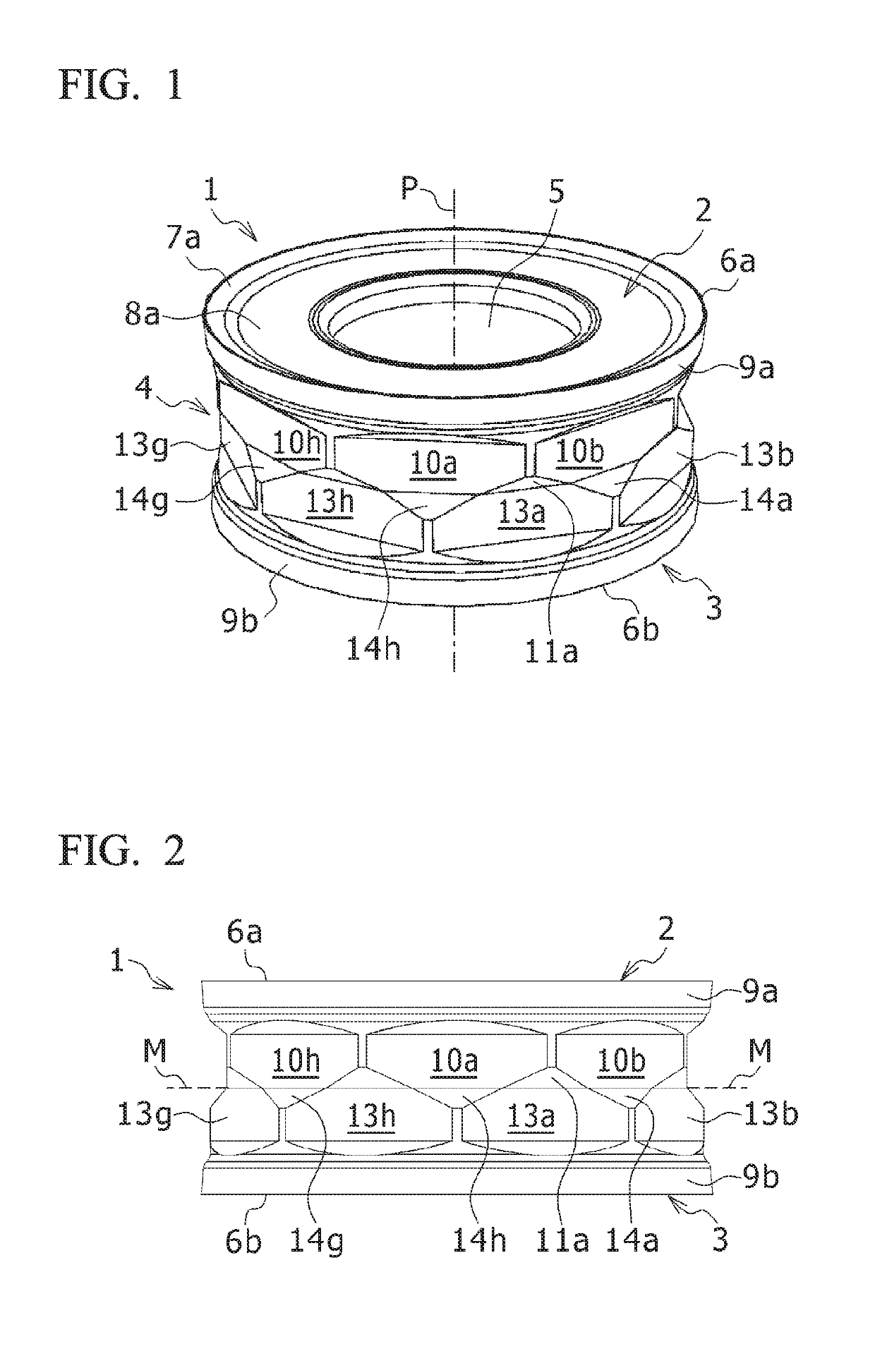
[0116]An embodiment of a double-sided circular cutting insert of the present invention will be described with reference to the drawings. FIG. 1 is a perspective view showing a first embodiment of the circular cutting insert of the present invention and FIG. 2 is a side view of the circular cutting insert 1 shown in FIG. 1.

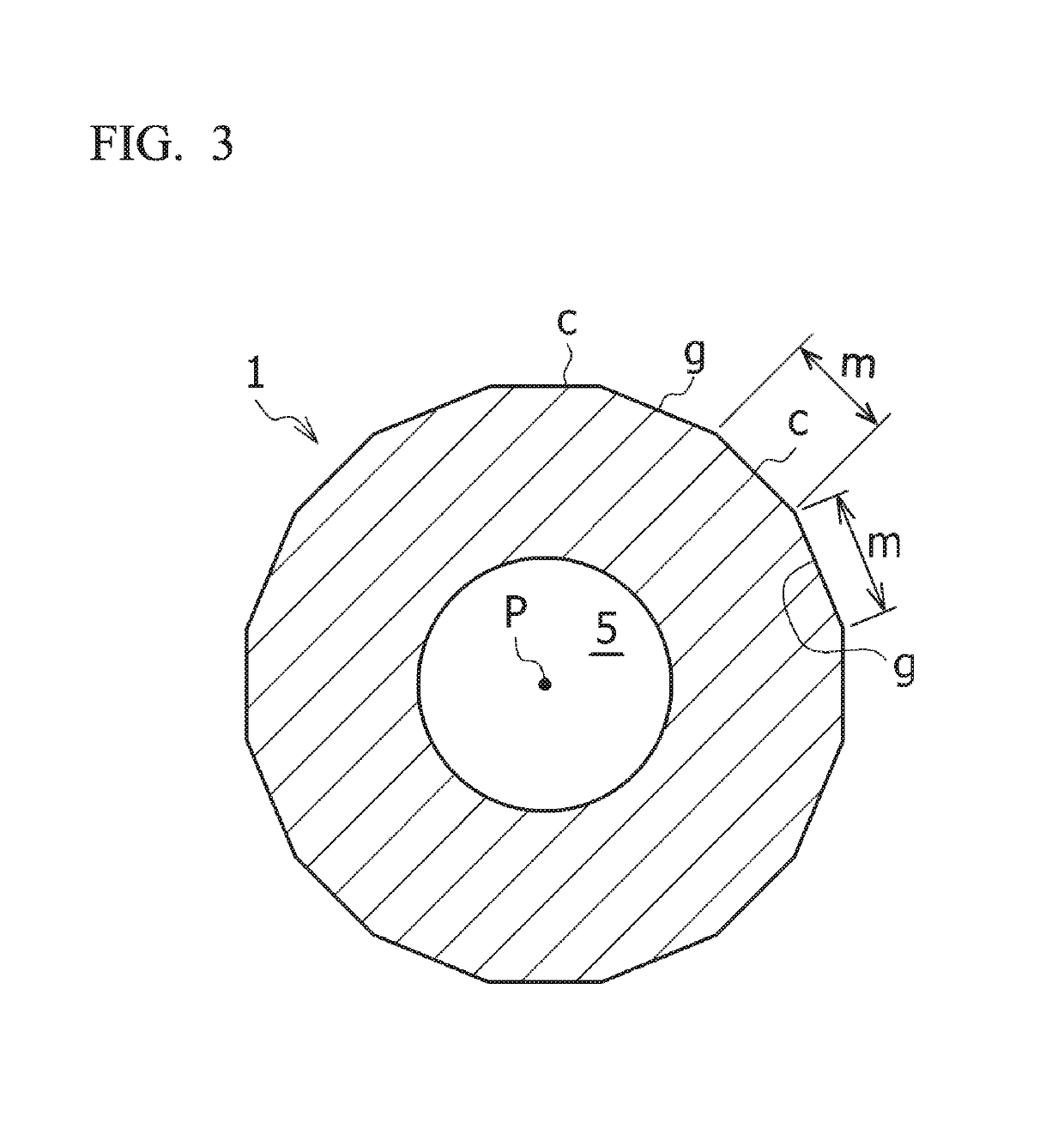
[0117]As shown in FIGS. 1 and 2, a basic configuration of the circular cutting insert 1 of the present embodiment includes: a top surface 2 formed into a circular shape in a planar view; a bottom surface 3 disposed at a position opposite to the top surface 2 and formed into a circular shape in a planar view; a side surface 4 connecting the top surface 2 and the bottom surface 3 to each other; a screw insertion hole 5 penetrating from the top surface 2 to the bottom surface 3; and cutting edges 6a and 6b formed along circular intersecting ridgelines at which the top surface 2 and the bottom surface 3 intersect with ...

second embodiment

[0185](Second Embodiment of Circular Cutting Insert)

[0186]Next, a second embodiment of the circular cutting insert of the present invention will be described. FIG. 8 is a perspective view of a circular cutting insert 25 according to the second embodiment, FIG. 9 is a side view of the circular cutting insert 25, and FIG. 10 is an enlarged view of the side view shown in FIG. 9. The cutting insert 25 according to the second embodiment is mainly different from the cutting insert 1 according to the above-described first embodiment as described in the following (1) and (2). In addition, the same reference numerals are assigned to configurations which are the same as those of the first embodiment, and descriptions thereof are omitted.

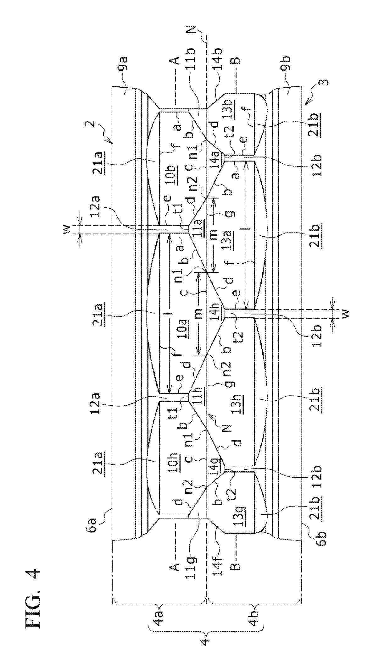
[0187](1) In the second embodiment, in the eight planar restraining faces which are sequentially disposed on the upper side surface 4a and the lower side surface 4b of the side surface 4 in the circumferential direction, the ridgelines (side a and side e) whic...

embodiment

[0201](Embodiment of Indexable Rotary Cutting Tool)

[0202]Next, in the indexable rotary cutting tool to which the above-described double-sided circular cutting insert of the present invention is attached, an embodiment thereof and a restraining structure for attaching the circular cutting insert to the insert mounting seat so as to restrain the circular cutting insert will be described with reference to FIGS. 11 to 16. Here, in the following descriptions of the indexable rotary cutting tool, a direction along a rotational axis of the indexable rotary cutting tool is referred to as an axial direction, a direction orthogonal to the rotational axis is referred to as a radial direction (radial direction of the tool main body), and a direction around the rotational axis is referred to as a circumferential direction (circumferential direction of the tool main body).

[0203]FIG. 11 is a perspective view showing an example of an indexable rotary cutting tool 30 according to the present embodim...


PUM


Abstract

In a circular cutting insert of the present invention, the upper side surface and the lower side surface each include: a plurality of planar restraining faces which are disposed sequentially in a circumferential direction of the upper side surface and the lower side surface so as to interpose a joint portion between each of the planar restraining faces and each have a side disposed on the side surface-intermediate line (N); and a plurality of antivibration restraining faces which are each disposed between two planar restraining faces adjacent through the joint portion and each include an inclined face, and the restraining faces of the lower side surface are disposed so as to be shifted with respect to the restraining faces of the upper side surface by a predetermined angle (α) around a central axis of a screw insertion hole.

Description

TECHNICAL FIELD[0001]The present invention relates to a cutting insert which is detachably attached to an indexable rotary cutting tool for performing milling and an indexable rotary cutting tool to which the cutting insert is attached, and particularly, to a double-sided circular cutting insert and an indexable rotary cutting tool having a means of preventing occurrence of vibrations during a cutting operation of a workpiece.[0002]Priority is claimed on Japanese Patent Application No. 2015-129520, filed on Jun. 29, 2015, the content of which is incorporated herein by reference.BACKGROUND ART[0003]In a cutting insert formed into a circular shape in a planar view, that is, in a so-called a circular (round) cutting insert, a top surface as a rake face and a bottom surface formed at a position opposite to the top surface are formed into circular shapes, a side surface connecting the top surface and the bottom surface to each other is formed into an approximately columnar shape or an ap...

Claims


Application Information

Patent Timeline
Patent Type & Authority Patents(United States)
IPC IPC(8): B23C5/06B23C5/22
CPCB23C5/2213B23C5/06B23C5/2221B23C2200/045B23C2210/244B23C2200/128B23C2200/361B23C2210/165B23C2210/168B23C2200/125
Inventor TAKAHASHI, HAYATO
Owner HITACHI TOOL ENG LTD
Why Eureka
Try Eureka