Wind turbine provided with a slat assembly

a technology assembly parts, which is applied in the direction of wind turbines, engine components, wind energy generation, etc., can solve the problems of reducing the efficiency exceeding the additional manufacturing costs. , to achieve the effect of increasing the effectiveness or performance of wind turbine blades, and increasing the effectiveness of wind turbines

Active Publication Date: 2019-07-16
LM WP PATENT HLDG
View PDF45 Cites 0 Cited by
  • Summary
  • Abstract
  • Description
  • Claims
  • Application Information

AI Technical Summary

Benefits of technology

[0007]As the requirement for effectiveness of a wind turbine is increased, there is a need for increasing the effectiveness or performance of profiled contours or wind turbine blades.
[0008]This is achieved by an aspect of the present invention which relates to a wind turbine blade for a rotor of a wind turbine having a substantially horizontal rotor shaft, the rotor comprising a hub from which the blade extends in a substantially radial direction when mounted to the hub. The wind turbine blade comprises a profiled contour defining a leading edge and a trailing edge, a pressure side and a suction side connecting the leading edge and the trailing edge, the profiled contour generating a lift when being impacted by an incident airflow. The blade further comprises a slat assembly located on the blade, the slat assembly comprising a slat device being supported by a support device positioning the slat device in a distance, i.e. with a spacing, from the surface of the blade. It is contemplated that the slat device improves the aerodynamic performance of the blade.

Problems solved by technology

This again results in problems when having to mount the blade to the hub, and, moreover, this causes great loads during operation of the blade, such as storm loads, due to the large surface area of the blade.
Due to the circular cross-section, the root region does not contribute to the energy production of the wind turbine and, in fact, lowers this a little because of drag.
Therefore, even small changes to the overall performance of the wind turbine blades may accumulate over the lifetime of a wind turbine blade to a high increase in financial gains, which surpasses the additional manufacturing costs relating to such changes.

Method used


Image

  • Wind turbine provided with a slat assembly
  • Wind turbine provided with a slat assembly
  • Wind turbine provided with a slat assembly

Examples


Embodiment Construction

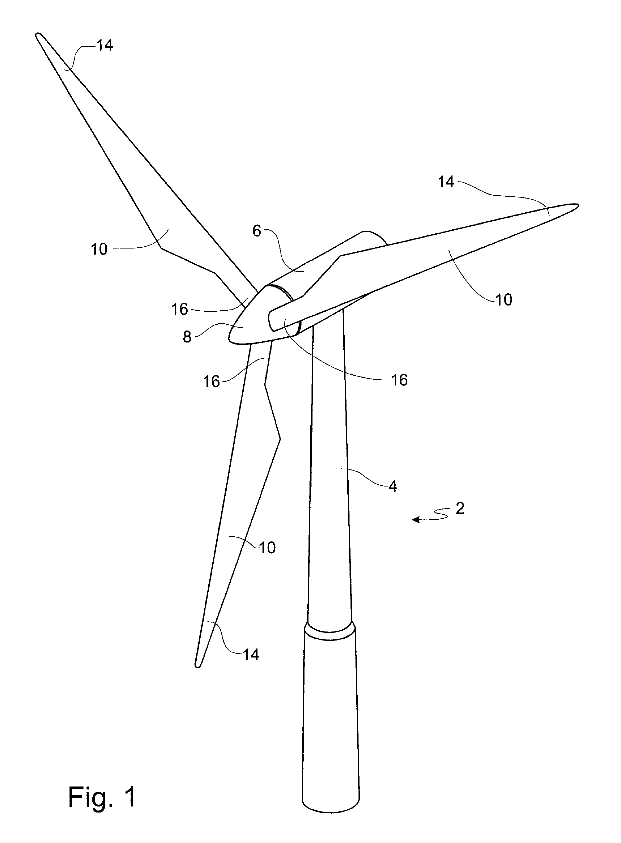
[0070]FIG. 1 is a schematic illustration of a conventional modern upwind wind turbine 2 according to the so-called “Danish concept” with a tower 4, a nacelle 6 and a rotor with a substantially horizontal rotor shaft. The rotor includes a hub 8 and three wind turbine blades 10 extending radially from the hub 8, each having a blade root 16 nearest the hub and a blade tip 14 furthest from the hub 8.

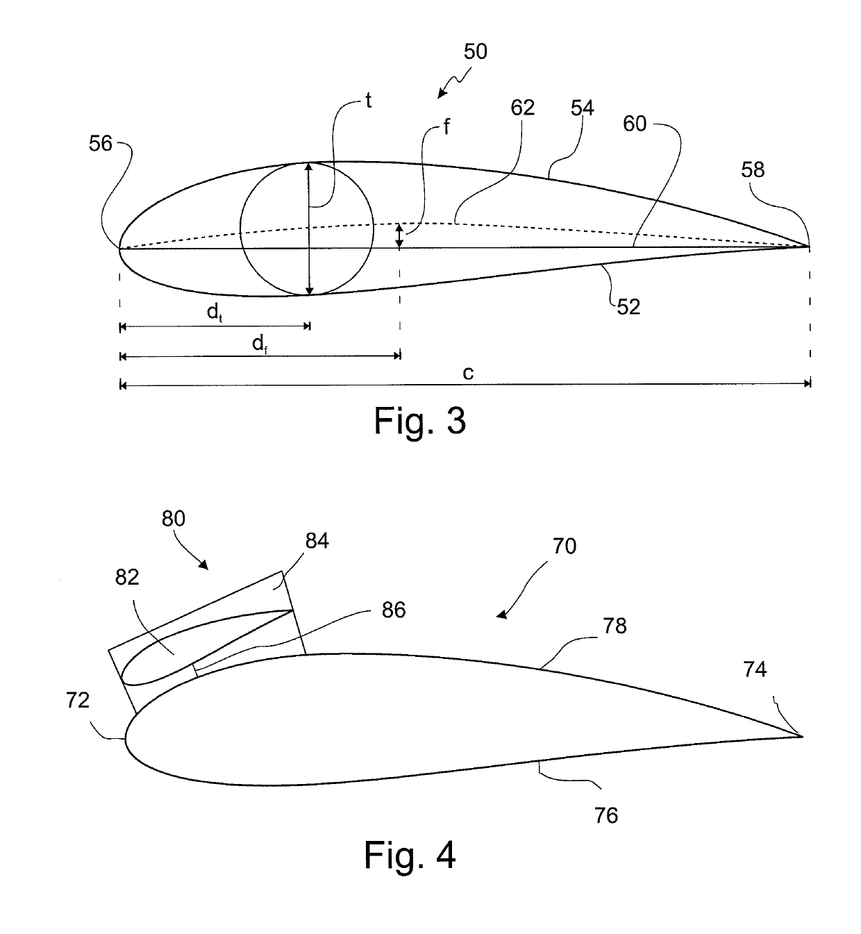
[0071]FIG. 3 shows a schematic view of an airfoil profile 50 of a typical blade or blade of a wind turbine depicted with the various parameters, which are typically used to define the geometrical shape of an airfoil. The airfoil profile 50 has a pressure side 52 and a suction side 54, which, during use, normally face the windward side and the leeward side, respectively, i.e. during rotation of the rotor. The airfoil 50 has a chord 60 with a chord length c extending between a leading edge 56 and a trailing edge 58 of the blade. The airfoil 50 has a thickness t, which is defined as the distanc...


PUM

PropertyMeasurementUnit
lengthaaaaaaaaaa
lengthaaaaaaaaaa
lengthaaaaaaaaaa

Abstract

The present invention relates to a wind turbine blade for a rotor of a wind turbine having a substantially horizontal rotor shaft, the rotor comprising a hub from which the blade extends in a substantially radial direction when mounted to the hub. The wind turbine blade comprises a profiled contour defining a leading edge and a trailing edge, a pressure side and a suction side connecting the leading edge and the trailing edge, the profiled contour generating a lift when being impacted by an incident air-flow, and a slat assembly located on the blade, the slat assembly comprising a slat device being supported by a support device positioning the slat device in a distance from the surface of the blade.

Description

[0001]This is a National Phase Application filed under 35 U.S.C. 371 as a national stage of PCT / EP2011 / 056633, filed on Apr. 27, 2011, and claims benefit from European Patent Application No. 10161196.0, filed on Apr. 27, 2010, the entire content of which is hereby incorporated by reference in its entirety.TECHNICAL FIELD[0002]The present invention relates to a wind turbine blade including a slat assembly. Further, the present invention relates to a blade or part of a blade for a rotor of a wind turbine having a substantially horizontal rotor shaft, the rotor comprising a hub, from which the blade extends substantially in a radial direction when mounted to the hub, the blade having a longitudinal direction with a tip end and a root end and a transverse direction, wherein the blade further comprises: a profiled contour including a pressure side and a suction side, as well as a leading edge and a trailing edge with a chord having a chord length extending there between, the profiled con...

Claims


Application Information

Patent Timeline
Patent Type & Authority Patents(United States)
IPC IPC(8): F03D1/06
CPCF03D1/0641F03D1/0633F03D1/0675Y10T29/49318F05B2240/301Y02E10/721F05B2240/30F05B2240/305Y02E10/72
Inventor LUND, BRIANJEREMIASZ, JEAN-GUILLAUMEJENSEN, LARS ERIKNIELSEN, MARTINANWAR, MOHAMMED MEHRAJRADHAKRISHNAN, SREERAM KOTTUMUKLU
Owner LM WP PATENT HLDG
Why Eureka
Try Eureka