Bidirectional gate valve

a gate valve and bi-directional technology, applied in the direction of valves, mechanical devices, basic electric elements, etc., can solve the problems of mechanical defects, deterioration of sealing precision, and increase of limitation in spatial restriction, so as to increase sealing precision of blades, high sealing properties, and high pressure

Active Publication Date: 2019-07-16
PRESYS
View PDF11 Cites 1 Cited by
  • Summary
  • Abstract
  • Description
  • Claims
  • Application Information

AI Technical Summary

Benefits of technology

[0020]As described so far, in accordance with the present invention, first and second mounting parts functioning as a cylinder for proving a driving force to horizontally move a blade are provided in a serial type, so that there is a merit in that the sealing precision of the blade is increased by providing a higher pressure than a parallel type link structure, and high sealing properties of the first and second passage holes can be ensured.
[0021]In addition, there is a merit in that the bidirectional gate valve has a width dimension relatively decreased due to the serial-type structure, so that the bidirectional gate valve may be manufactured in a compact type, and may thereby has less spatial limitation.

Problems solved by technology

Thus, there was a limitation in that a mechanical defect may occur when the sealing member is horizontally moved, for example, the precision of the sealing is deteriorated because the pressures of the first and second rotation driving parts 160 and 170 and the pressure of the first and second valve driving parts 180 and 190, which function as a cylinder, are smaller than the pressure of a serial-type cylinder.
In addition, since the first and second links 40 and 50 are positioned in the same plane, and the width dimensions of the first and second valve housings 20 and 30 are relatively increased, there was a limitation in that spatial restriction is increased because it is impossible to manufacture the bidirectional gate valve in a compact type.

Method used


Image

  • Bidirectional gate valve
  • Bidirectional gate valve
  • Bidirectional gate valve

Examples


Embodiment Construction

[0031]Hereinafter with reference to accompanying drawings, a bidirectional gate valve 1 in accordance with an embodiment of the present invention will be described in detail. First, it should be noted that in the drawings, like components or parts are represented by like reference numerals, if possible. In describing the present invention, when a detailed description about a related well-known function or configuration may obscure the gist of the present invention, the detailed description thereof will not be provided.

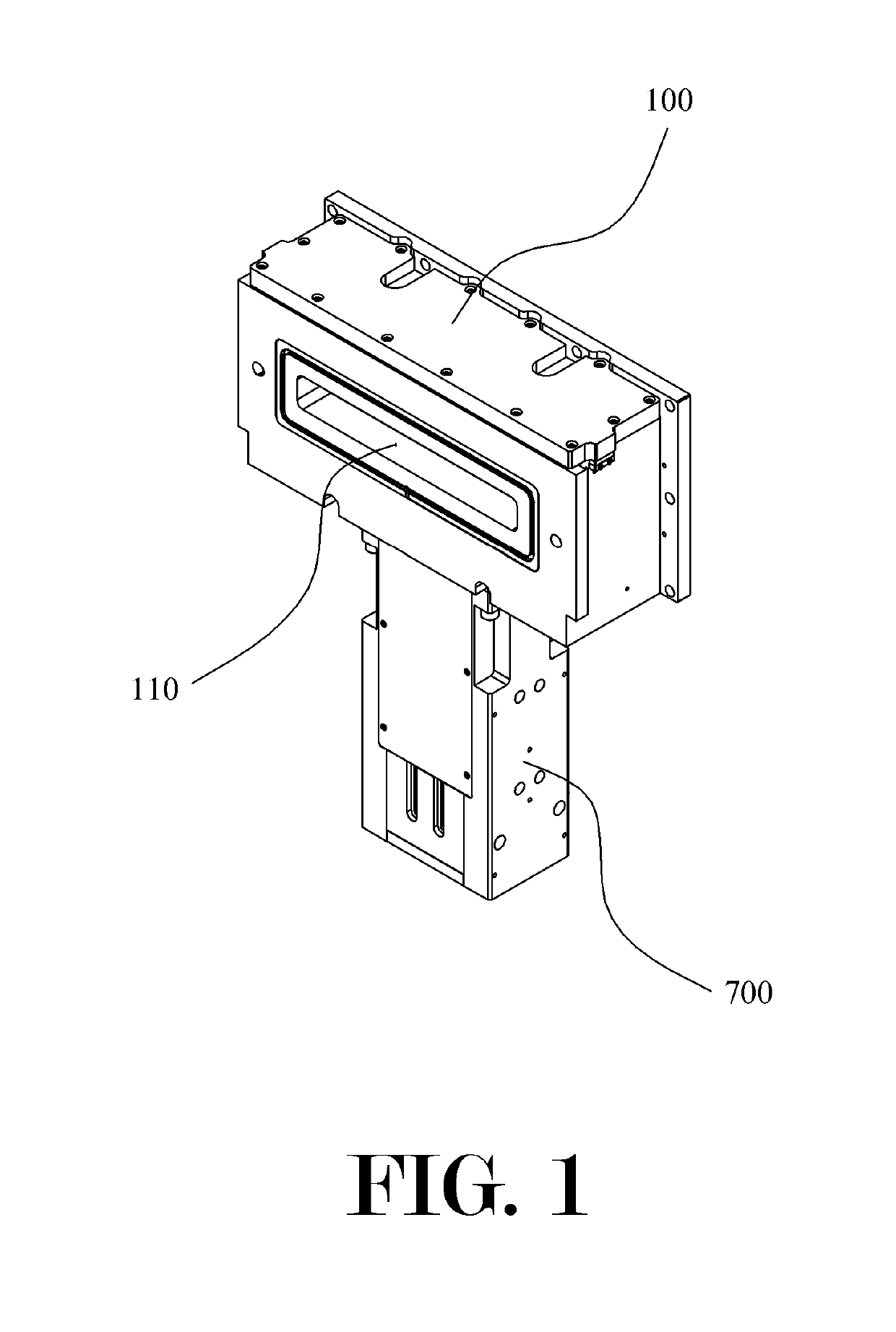
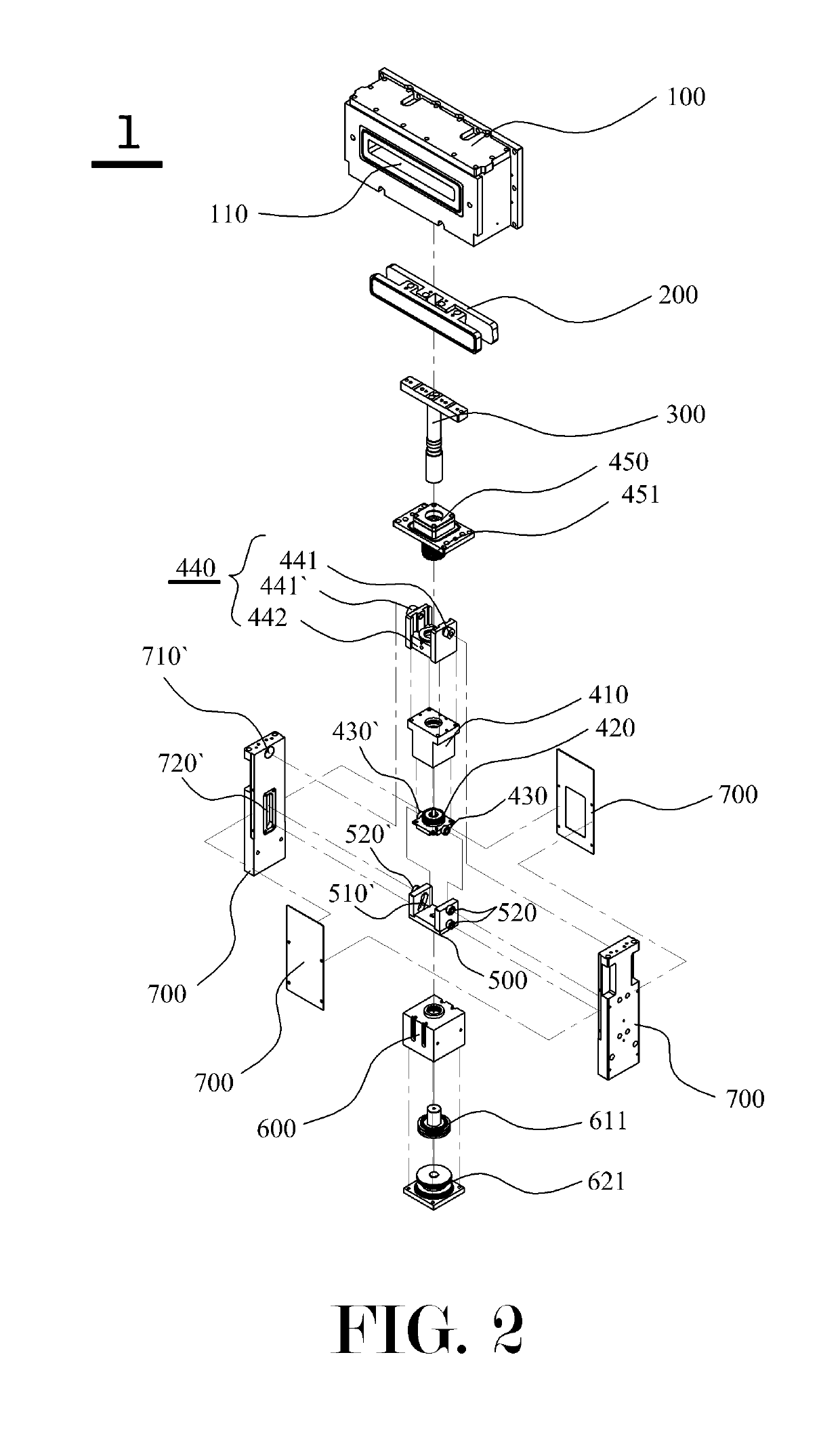
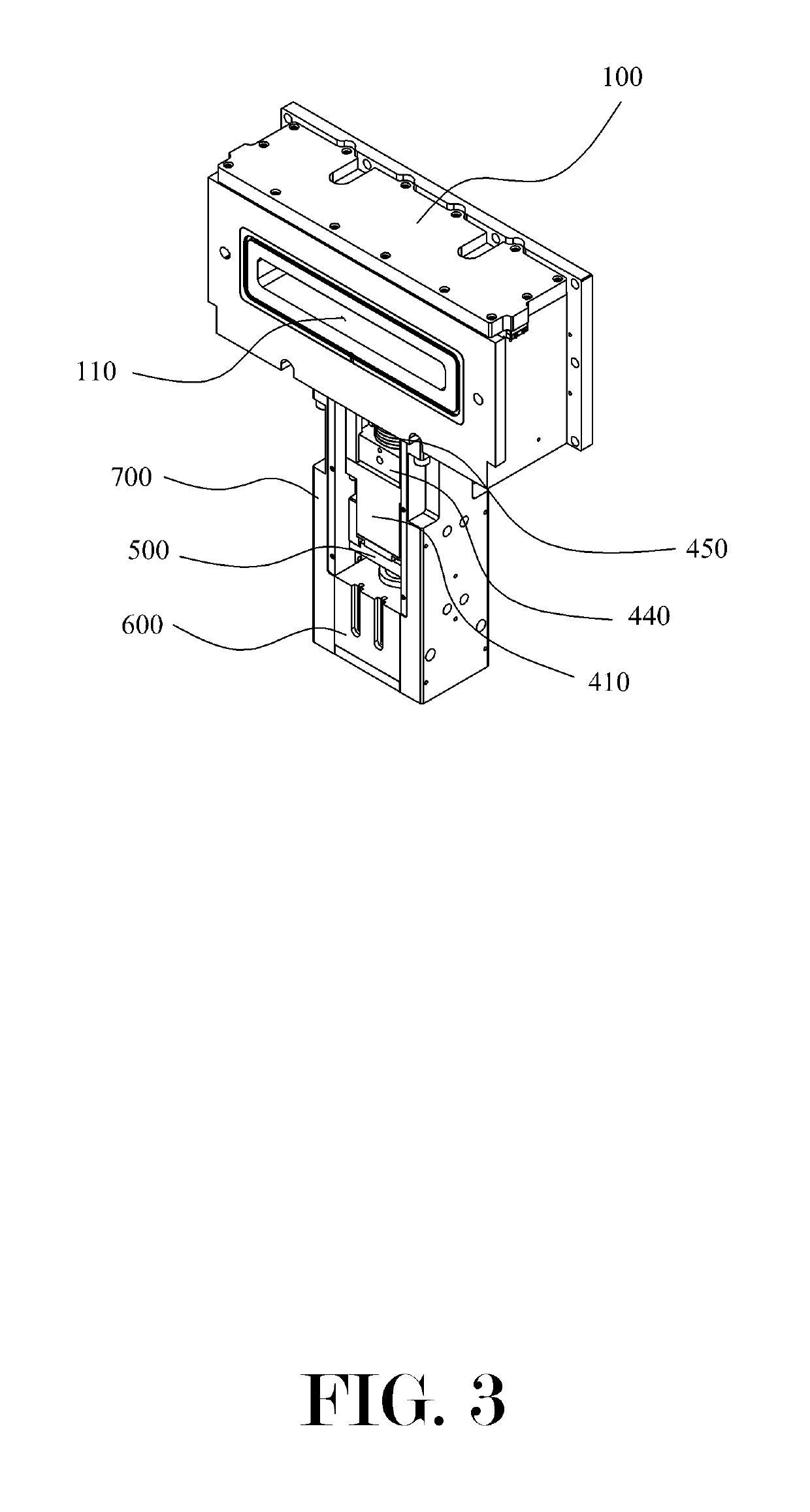
[0032]A bidirectional gate valve 1 in accordance with an embodiment of the present invention is roughly configured from a blade 200, a shaft 300, a first driving block 400, a second driving block 500, a third driving block 600, and a main body bracket 700.

[0033]Before moving to description, it should be noted that with respect to FIG. 7, the left and right sides are respectively described as the front and rear surfaces, a movement in the up-down direction is described ...


PUM


Abstract

A bidirectional gate valve including: a blade (200) installed in a valve housing (100) having first and second passage holes (110, 120) to open / close the first and second passage holes (110, 120); a shaft (300) coupled to a lower portion of the blade (200); a first driving block (400) including: a first cylinder (410) which is provided under the valve housing (100) and into which the shaft (300) is inserted; a first piston (420) installed inside the first cylinder (410) and coupled to a lower portion of the shaft(300) to vertically move the shaft (300) according to pressure change inside the first cylinder (410).

Description

[0001]This Application is a 35 U.S.C. 371 National Stage Entry of International Application No. PCT / KR2016 / 007484 filed on Jul. 11, 2016, which claims the benefit of Republic of Korea Patent Application No. 10-2015-0108583, filed on Jul. 31, 2015, the entire disclosures of which are incorporated by reference herein.TECHNICAL FIELD[0002]The present invention relates to a bidirectional gate valve, and particularly, to a bidirectional gate valve 1 which is characterized by including: a blade 200 installed inside a valve housing 100 having first and second passage holes 110 and 120, which respectively have an open front surface and an open rear surface, and configured to open / close the passage holes 110 and 120; a shaft 300 coupled to a lower portion of the blade 200; a first driving block 400 including: a first cylinder 410 which is provided under the valve housing 100 and into which the shaft 300 is inserted; a first piston 420 installed inside the first cylinder 410 and coupled to a ...

Claims


Application Information

Patent Timeline
Patent Type & Authority Patents(United States)
IPC IPC(8): F16K51/02F16K3/02F16K3/18H01L21/02F16K3/314
CPCF16K51/02F16K3/02F16K3/0245F16K3/314H01L21/02F16K3/18H01L21/02367F16K31/52475F16K31/5286F16K3/0254F16K3/184
Inventor KIM, BAE-JINCHOI, KI SUNKIM, KANG HYUNKIM, SANG MIN
Owner PRESYS
Why Eureka
Try Eureka