Method for measuring wear of railroad vehicle wheel flange

a technology for railroad vehicles and flanges, which is applied in the direction of railway components, transportation and packaging, instruments, etc., can solve the problems of difficult implementation of these technologies, affecting the ability of railroad vehicles to move, and complex specifications, etc., and achieves the effect of controlling the amount of wheel flange wear, detecting quickly the wheel flange wear, and exceeding the control rang

Inactive Publication Date: 2019-07-16
NIPPON STEEL CORP
View PDF22 Cites 20 Cited by
  • Summary
  • Abstract
  • Description
  • Claims
  • Application Information

AI Technical Summary

Benefits of technology

[0030]The present invention makes it possible to control the amount of wheel flange wear by directly measuring the amount of wear of wheel flange wear of a railroad vehicle online during travel through a curved section.
[0031]Moreover, according to the present invention, because it is possible to quickly find wheels having flange wear that has exceeded a control range, it becomes possible to obtain very advantageous effects in ensuring safety when a railroad vehicle is traveling through a curved section.

Problems solved by technology

When the wheel becomes worn due to contact with the rail, it greatly affects the ability of the railroad vehicle to move.
However, the art disclosed in Patent References 1-3 are not technologies for making measurements while a vehicle is traveling, but rather, they are technologies for making offline measurements.
It is therefore difficult to implement these technologies in a timely manner to ensure safety while a vehicle is traveling.
Consequently, the specifications are complex and maintenance requires a lot of steps.
Moreover, the measured values have to be processed separately, making it difficult to implement these technologies in a timely manner to ensure safety while a vehicle is traveling.

Method used


Image

  • Method for measuring wear of railroad vehicle wheel flange
  • Method for measuring wear of railroad vehicle wheel flange
  • Method for measuring wear of railroad vehicle wheel flange

Examples


example

[0044]Following is a description of an example of the method for measuring wear of a railroad vehicle wheel flange according to the present invention, making reference to FIG. 1 to FIG. 8.

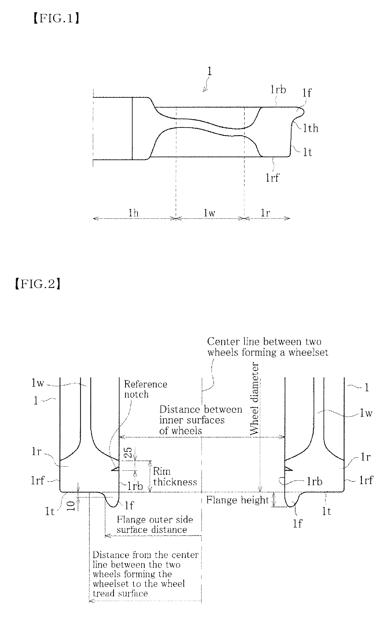
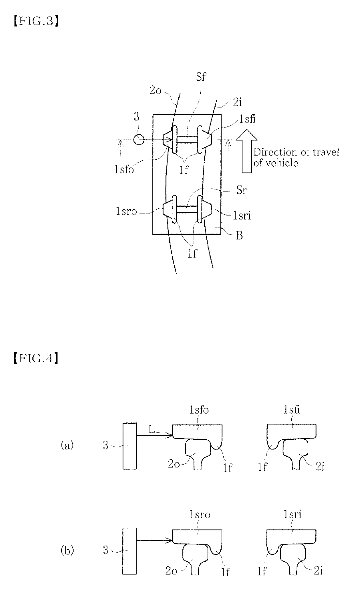
[0045]FIG. 1 is a drawing that indicates the principal sites on a railroad vehicle wheel. A wheel 1 is formed from three parts: a wheel boss 1h into which is inserted an axle; a rim 1r that makes contact with a rail 2; and a plate 1w that connects the boss 1h and the rim 1r.

[0046]On an outer periphery of the rim 1r are formed a tread 1t that makes contact with the rail 2 and a flange 1f that is continued to the tread 1t via a throat 1h. A side surface of the rim 1r on a side where the flange 1f is formed is referred to as a back rim surface 1rb, and a side surface on a side opposite to the back rim 1rb is referred to as a front rim surface 1rf.

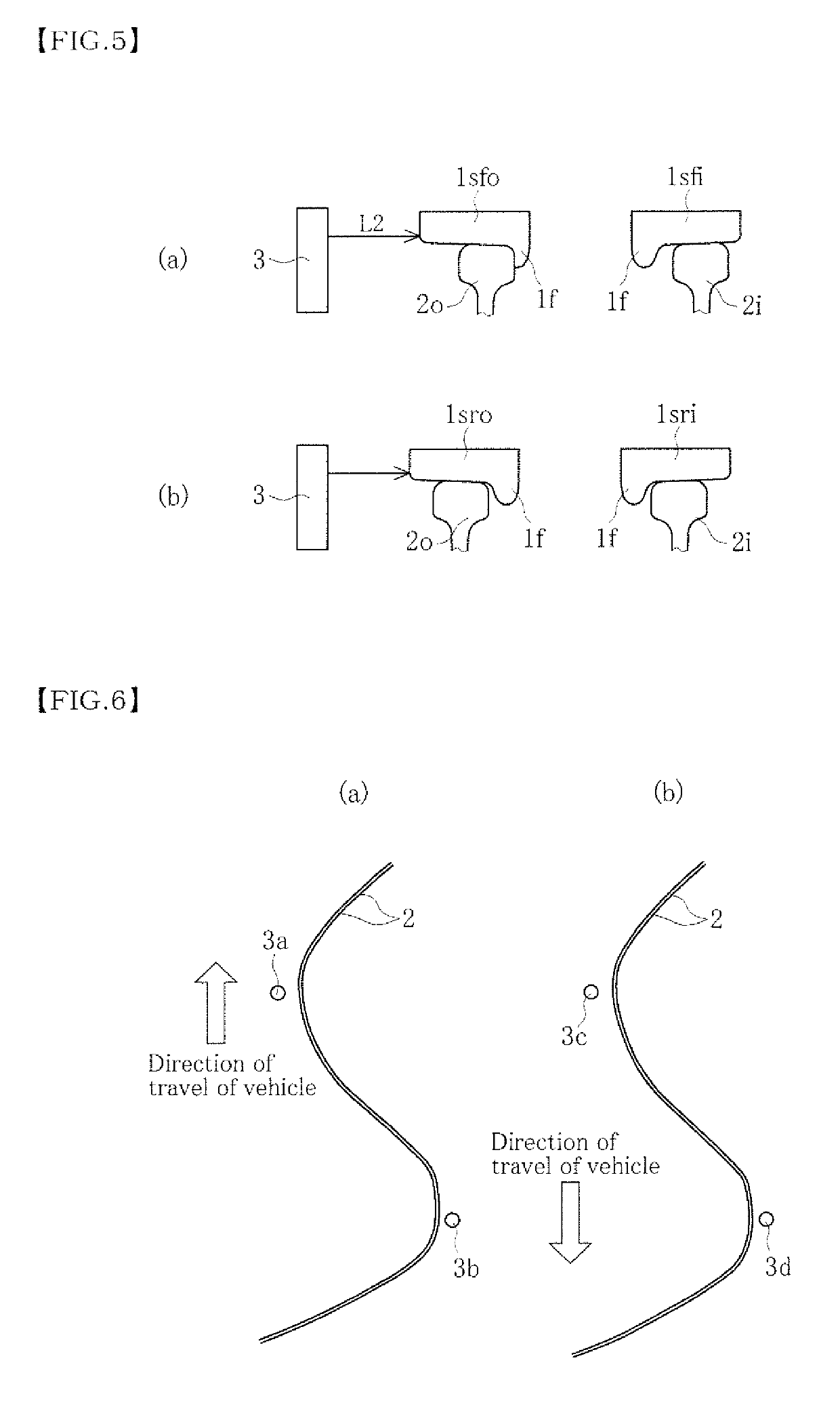
[0047]In general, when a railroad vehicle is traveling through a curved section with a radius of curvature of 800 m or less, as described above, the throat...


PUM


Abstract

An amount of wear of a railroad vehicle wheel flange online while traveling in a curved section is directly measured. A laser rangefinder 3 is installed on an outer track side in a rounded curve section of a railroad track. When a railroad vehicle travels through the rounded curve section, the laser rangefinder 3 measures a distance to a front rim surface of a wheel on an outer track side of a wheelset in a forward direction of travel of a bogie forming a vehicle. The amount of wheel flange wear is obtained by comparing this measured distance with a previous measurement of the measured distance. It is then possible to control the amount of wheel flange wear when traveling in a curved section, thus making it possible to quickly find wheels having flange wear that has exceeded a control range and ensure safety during travel of the railroad vehicle.

Description

TECHNICAL FIELD[0001]The present invention relates to a method for directly measuring an amount of wear of a railroad vehicle wheel flange online during travel.BACKGROUND ART[0002]A railroad vehicle wheel makes contact with a rail during travel. When the wheel becomes worn due to contact with the rail, it greatly affects the ability of the railroad vehicle to move. It is therefore very important to control the amount of wear of the wheels in order to ensure safe travel of the railroad vehicle.[0003]FIG. 10 schematically illustrates how a wheel 1 receives a force from a rail 2 during travel along a curved section formed from a gentle curve and a rounded curve. On the left-hand side of FIG. 10, the rail 2 is on an outer periphery of the curved section, and on the right-hand side of FIG. 10, the rail 2 is on an inner periphery of the curved section. Below, the outer periphery of the curved section is referred to as an outer track side, and the inner periphery of the curved section is r...

Claims


Application Information

Patent Timeline
Patent Type & Authority Patents(United States)
IPC IPC(8): G01M17/10B61K9/12G01B21/02
CPCG01M17/10B61K9/12G01B21/02B61L27/57
Inventor KONDO, OSAMUSHIMOKAWA, YOSHIYUKI
Owner NIPPON STEEL CORP
Why Eureka
Try Eureka