
Methods and systems for modifying user influence during a collaborative session of real-time collective intelligence system

a real-time closed-loop collective intelligence and user influence technology, applied in the field of collaborative intelligence systems and methods, can solve problems such as inability to meet the needs of users, and affecting the collective intelligence of human groups

Active Publication Date: 2019-07-16
UNANIMOUS A I
View PDF105 Cites 14 Cited by
  • Summary
  • Abstract
  • Description
  • Claims
  • Application Information

AI Technical Summary

Benefits of technology

The invention provides a method for adjusting a user's intent vector during a collaboration session with multiple computers and a collaborative server. The method uses the user's intent vector to determine the direction and magnitude of their input in real-time. By adjusting the user's intent vector based on the direction history and the direction of the current user's choice, the method can adapt the user's preferences during the collaboration session. This allows for more efficient and effective collaboration among the multiple users.

Problems solved by technology

Still, the current art has some deficiencies.
One deficiency is the fact that participating users in a real-time closed-loop collective intelligence systems may sometimes be excessively influenced by other users in the system, rather than expressing their own individual will, wisdom, or intent.
This is known as “social influence bias” and has been shown to have negative effects on the collective intelligence of human groups.
A related deficiency of the present art is that participants within human swarms sometimes do not convey their individual conviction level with respect to a set of options currently under group deliberation with enough expressiveness to clearly differentiate the varying levels of conviction among users.

Method used


Image

  • Methods and systems for modifying user influence during a collaborative session of real-time collective intelligence system
  • Methods and systems for modifying user influence during a collaborative session of real-time collective intelligence system
  • Methods and systems for modifying user influence during a collaborative session of real-time collective intelligence system

Examples


second embodiment

[0184]With respect to FIG. 13, the method is described that generates faction data but does not always accurately reflect the faction representation. FIG. 14 shows the method of generating faction data which can more accurately reflect faction representation using a novel method.

first embodiment

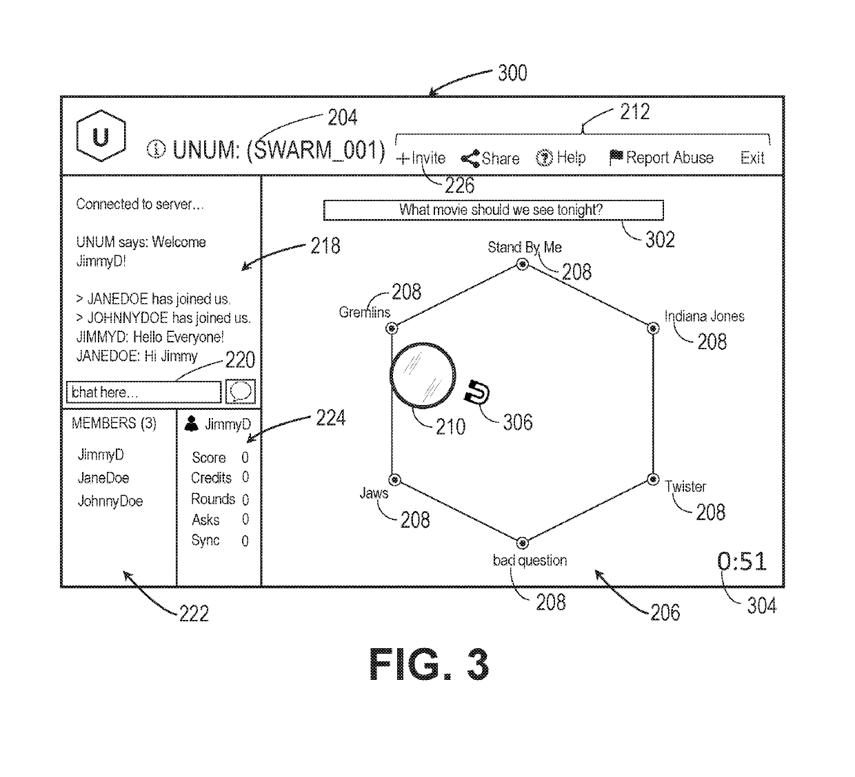
[0185]Referring next to FIG. 12, a flowchart for a method of faction determination is shown in FIG. 12. In related FIG. 13, the target areas 900, 1000, 1100 of FIGS. 9-11 are shown including faction spatial regions in accordance with the method of faction determination of FIG. 12. Shown are the pointer 210, the plurality of magnet icons 306, the answer choices 208, the plurality of selection targets 902, 904, 906, 908, 910, 912, a first Faction Associated Spatial Region (FASR) 1300, a second FASR 1302, a third FASR 1304, a fourth FASR 1306, a fifth FASR 1308, a sixth FASR 1310, and a plurality of vertex angles 1312.

[0186]The method for determining faction analysis data is described wherein the CCS 102 is configured to define a plurality of spatial regions, each spatial region associated with a unique one of the plurality of possible factions that user can join if pulling towards one of the plurality of available answer choices 208. These regions are called Faction Associated Spatial...


PUM


Abstract

Systems and methods for real-time collaborative computing and collective intelligence are disclosed. A collaborative application runs on a collaborative server connected to a plurality of computing devices. Collaborative sessions are run wherein a group of independent users, networked over the internet, collaboratively answer questions in real-time, thereby harnessing their collective intelligence. Methods are disclosed for, during a collaborative session, real-time changing of the amount of influence the user has on determining the collaborative answer.

Description

[0001]This application claims the benefit of U.S. Provisional Application No. 62 / 358,026 entitled METHODS AND SYSTEMS FOR AMPLIFYING THE INTELLIGENCE OF A HUMAN-BASED ARTIFICIAL SWARM INTELLIGENCE, filed Jul. 3, 2016, which is incorporated in its entirety herein by reference.[0002]This application is a continuation-in-part of U.S. application Ser. No. 14 / 668,970 entitled METHODS AND SYSTEMS FOR REAL-TIME CLOSED-LOOP COLLABORATIVE INTELLIGENCE, filed Mar. 25, 2015, which in turn claims the benefit of U.S. Provisional Application 61 / 970,885 entitled METHOD AND SYSTEM FOR ENABLING A GROUPWISE COLLABORATIVE CONSCIOUSNESS, filed Mar. 26, 2014, both of which are incorporated in their entirety herein by reference.[0003]This application is a continuation-in-part of U.S. application Ser. No. 14 / 708,038 entitled MULTI-GROUP METHODS AND SYSTEMS FOR REAL-TIME MULTI-TIER COLLABORATIVE INTELLIGENCE, filed May 8, 2015, which in turn claims the benefit of U.S. Provisional Application 61 / 991,505 ent...

Claims


Application Information

Patent Timeline
Patent Type & Authority Patents(United States)
IPC IPC(8): G06F3/01G06Q50/00G06F3/0482G06F3/0484G06Q10/10H04L29/08G06F3/0481
CPCG06F3/0482G06F3/011G06F3/04812G06F3/04842G06Q10/101G06Q50/01H04L67/22H04L67/10H04L67/12H04L67/14H04L67/141H04L67/143H04L67/18H04L67/04H04L67/52H04L67/535
Inventor ROSENBERG, LOUIS B.
Owner UNANIMOUS A I
Learn More