Control circuit and control method for switch circuit and switching-mode power supply circuit

a control circuit and power supply circuit technology, applied in the field of electronic circuit technologies, can solve the problems of short circuit transient response, long time-consuming and laborious, and long time-consuming, and achieve the effect of increasing the inductance current more rapidly, shortening the turn-off time of the main switch transistor, and increasing the curren

Active Publication Date: 2019-07-16
JOULWATT TECH INC LTD
View PDF4 Cites 0 Cited by
  • Summary
  • Abstract
  • Description
  • Claims
  • Application Information

AI Technical Summary

Benefits of technology

[0011]detecting the output current in a switch circuit of a constant current output, and increasing the upper limit value and the lower limit value of the inductor current when the output current may be lower than the preset reference current; and decreasing the upper limit value and the lower limit value of the inductor current when the output current may be higher than the preset reference current.
[0037]Using the control method and control circuit for the switch circuit and the switching-mode power supply circuit including the control circuit provided by the present invention, when the output voltage or the output current jumps from a small value to a large value, the inductor current can reach the lower limit value of the inductor current earlier than in a steady state, so that the turn-off time of the main switch transistor can become shorter and the turn-on time can become longer. Furthermore, there is no limitation on the maximum turn-on time in this control method, so that the inductor current can be increased more rapidly. Therefore, when the load current is increased, the inductor current is fast in response without overshoot, the output voltage drops little, there is no overshoot in the process of voltage recovery, and the circuit is fast in transient response. On the contrary, when the output voltage or the output current jumps from a large value to a small value, the inductor current cannot reach the lower limit value of the inductor current, so that the main switch transistor may be switched off all the time until the inductor current reaches the lower limit value of the inductor current. Further, there is no limitation on the minimum turn-on time in this control method, so that there is no limitation on the turn-off time of the main switch transistor, and the inductor current can be decreased more rapidly. Therefore, when the load current is decreased, the inductor current is fast in response without overshoot, the overshoot of the output voltage is little, and the circuit is fast in transient response.

Problems solved by technology

However, the circuit is slow in transient response.
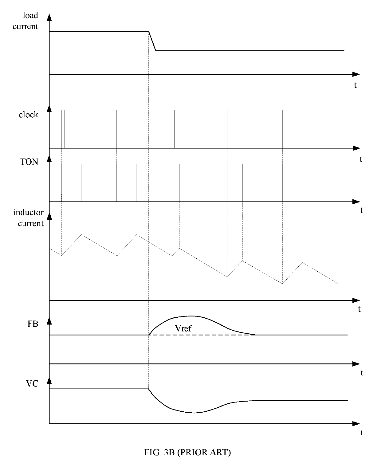
When a jump occurs in an output load, the output voltage may exhibit overshoot and drop for a long time.
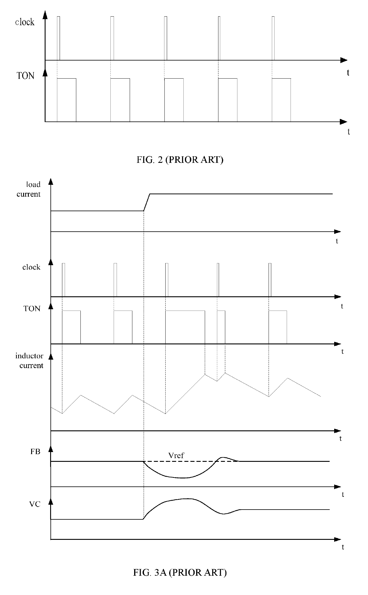
However, the main switch transistor M00 may not be switched on until the rising edge of the clock signal appears, while, at this moment, the output voltage has dropped to a lower value due to the increase of the load current, and there is limitation on the maximum turn-on time of the main switch transistor M00 (the maximum turn-on time is shorter than a clock cycle due to the presence of the clock signal).
Therefore, not only current overshoot may occur in the inductor current, but also the output voltage may drop largely.
Furthermore, the overshoot may be easily generated in the process of voltage recovery, and the circuit is relatively slow in transient response.
Therefore, the overshoot of the output voltage is relatively large, and the circuit is relatively slow in transient response.
As can be seen, an existing switch circuit is slow in transient response in the process of achieving the fixed frequency control of the clock signal, and when a jump occurs in the output load, the output voltage may exhibit overshoot and drop for a long time.

Method used


Image

  • Control circuit and control method for switch circuit and switching-mode power supply circuit
  • Control circuit and control method for switch circuit and switching-mode power supply circuit
  • Control circuit and control method for switch circuit and switching-mode power supply circuit

Examples


Embodiment Construction

[0054]With reference to the accompanying drawings, the foregoing and additional technical features and advantages of the present invention are described clearly and completely below. Obviously, the described embodiments are only a part of the embodiments of the present invention and not all embodiments.

[0055]An embodiment of the present invention provides a control method for a switch circuit, as shown in FIG. 4A, and the method includes following steps:

[0056]S100: detecting an output voltage or an output current in a circuit, and increasing an upper limit value and a lower limit value of an inductor current when the output voltage is lower than a preset reference voltage or the output current is lower than a preset reference current; and decreasing the upper limit value and the lower limit value of the inductor current when the output voltage is higher than the preset reference voltage or the output current is higher than the preset reference current; and

[0057]S200: sampling the in...


PUM


Abstract

The present invention provides a control circuit and a control method for a switch circuit and a switching-mode power supply circuit. The control method comprises following steps: detecting an output voltage or an output current, and adjusting an upper limit value and a lower limit value of an inductor current according to a result of comparing the output voltage or the output current with the corresponding reference; and sampling the inductor current, and controlling a main switch transistor in the circuit to be switched off when a sampling current rises to the upper limit value, and controlling the main switch transistor to be switched on when the sampling current drops to the lower limit value. In the present invention, the inductor current is fast in response without overshoot, the output voltage drops very little, there is no overshoot in a process of voltage recovery, and circuit transient response is fast.

Description

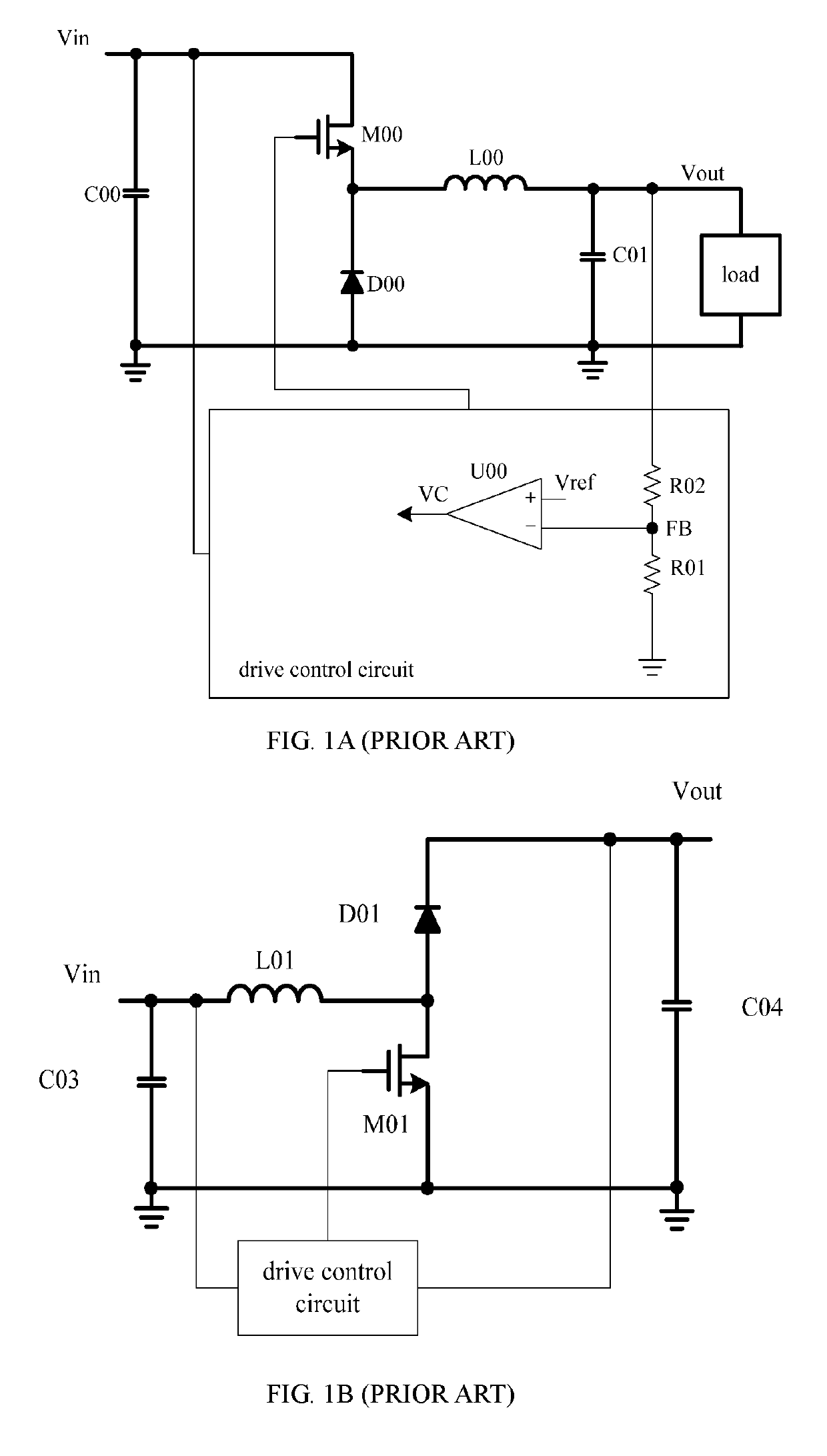
CROSS-REFERENCE TO RELATED APPLICATIONS[0001]This Non-provisional application claims priority under 35 U.S.C. § 119(a) on Patent Application No(s). 201610780506.8 filed in People's Republic of China on Aug. 31, 2016, the entire contents of which are hereby incorporated by reference.BACKGROUND OF THE INVENTIONField of the Invention[0002]The present invention relates to the field of electronic circuit technologies, and more particularly, to a control circuit and a control method for a switch circuit and a switching-mode power supply circuit.Description of the Related Art[0003]An existing switch circuit controls an output voltage by controlling switch-on or switch-off of a switch transistor. A common switch circuit includes a BUCK (step-down) circuit (as shown in FIG. 1A) and a BOOST (step-up) circuit (as shown in FIG. 1B). In a fixed frequency control mode, a control circuit is driven to generate a clock signal with a fixed frequency, and a main MOS is switched on at a rising edge of ...

Claims


Application Information

Patent Timeline
Patent Type & Authority Patents(United States)
IPC IPC(8): H02M3/335H02M1/36H02M3/156H03K17/042H02M1/096H02M3/07H02M1/00
CPCH02M3/33523H02M1/096H02M1/36H03K17/04206H02M3/156H02M2003/072H02M2001/0009H02M1/08H02M1/0003H02M1/0009H02M3/072
Inventor WONG, PITLEONGCHAN, SIOPANGREN, YUANCHENGZHOU, XUNWEI
Owner JOULWATT TECH INC LTD
Why Eureka
Try Eureka