Light guide composition, backlight module having light guide composition and display device having backlight module
a technology of light guide and composition, which is applied in the field of light guide elements, can solve the problems that light with a shorter light wavelength (such as blue light) is likely to be absorbed by the light guide plate, and achieve the effect of increasing reducing the propagation distance of light with a longer light wavelength
- Summary
- Abstract
- Description
- Claims
- Application Information
AI Technical Summary
Benefits of technology
Problems solved by technology
Method used
Image
Examples
first embodiment
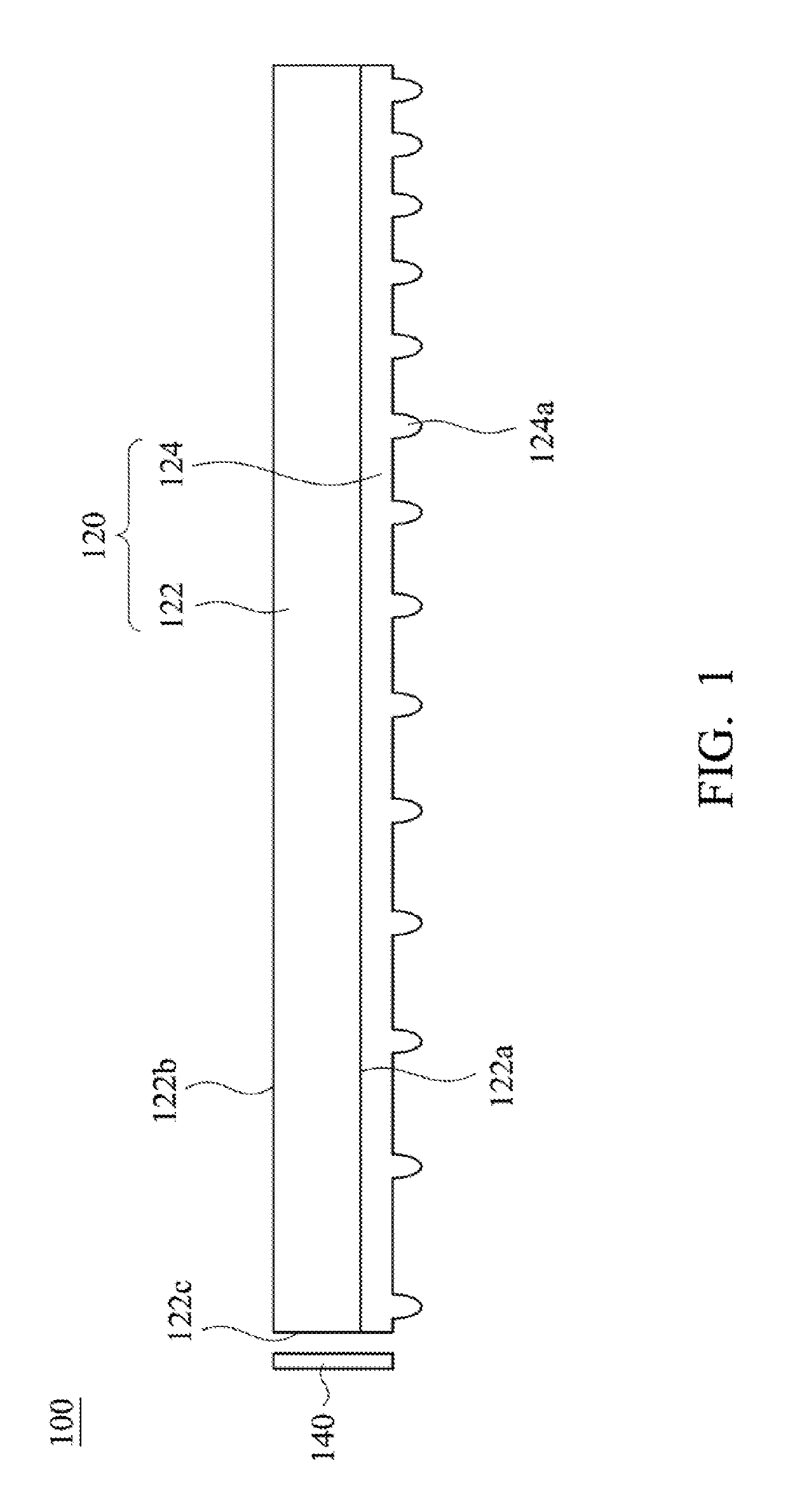
[0037]Referring to FIG. 1, FIG. 1 is a schematic structural diagram showing a backlight module 100 in accordance with the present invention. The backlight module 100 of the present embodiment mainly includes a light guide composition 120 and a light source 140. The light source 140 is used to provide light to the light guide composition 120, and the light guide composition 120 can refract and reflect light generated from the light source 140, so as to increase luminance value and uniform illumination color of the backlight module 100.
[0038]It should be noted that, the light guide composition 120 can be a light guide film which has the same thickness as the light source 140 or has smaller thickness than the light source 140, so as to meet the trends of compactness and thickness of backlight modules. When the light guide composition 120 is used in the field of lamp industry, the light guide composition 120 is not required to meet the requirements of compactness and thickness for backl...
second embodiment
[0048]Referring to FIG. 6, FIG. 6 is a schematic structural diagram showing a backlight module 200 in accordance with the present invention. Structure of the backlight module 200 of the present embodiment is similar to that of the backlight module 100, and the main difference therebetween is that a light guide composition 220 of the backlight module 200 has different structure. As shown in FIG. 6, the light guide composition 220 includes a substrate 222 and a first microstructure layer 224 disposed on the substrate 222. The first microstructure layer 224 includes plural first microstructures 224a, and each of the first microstructures 224a is a V-shaped strip structure. As shown in FIG. 6, an extending direction of the first microstructures 224a is parallel to an extending direction of a light-incident surface 222a of the substrate 222, thereby achieving the same effect as described above, which will not be described herein.
third embodiment
[0049]Referring to FIG. 7, FIG. 7 is a schematic structural diagram showing a backlight module 300 in accordance with the present invention. Structure of the backlight module 300 of the present embodiment is similar to that of the backlight module 100, and the main difference therebetween is that a light guide composition 320 of the backlight module 300 has different structure. As shown in FIG. 7, the light guide composition 320 includes a substrate 322, a first microstructure layer 324 and a second microstructure layer 326. The substrate 322 has a first main surface 322a, a second main surface 322b and a light-incident surface 322c. The first main surface 322a is opposite to the second main surface 322b, and the light-incident surface 322c connects the first main surface 322a and the second main surface 322b. Moreover, the first microstructure layer 324 and the second microstructure layer 326 are respectively disposed on the first main surface 322a and the second main surface 322b....
PUM
 Abstract
Description
Claims
Application Information
 - R&D
- Intellectual Property
- Life Sciences
- Materials
- Tech Scout
- Unparalleled Data Quality
- Higher Quality Content
- 60% Fewer Hallucinations
Browse by: Latest US Patents, China's latest patents, Technical Efficacy Thesaurus, Application Domain, Technology Topic, Popular Technical Reports.
© 2025 PatSnap. All rights reserved.Legal|Privacy policy|Modern Slavery Act Transparency Statement|Sitemap|About US| Contact US: help@patsnap.com


