Power supply apparatus

a power supply and power supply technology, applied in the direction of dc-ac conversion without reversal, manufacturing tools, instruments, etc., can solve the problems of increasing the number, increasing the cost of the apparatus, and affecting the operation of the apparatus, so as to reduce the number of components required, simplify the circuit arrangement, and eliminate the effect of imbalan

Active Publication Date: 2019-07-23
SANSHA ELECTRIC MFG
View PDF12 Cites 4 Cited by
  • Summary
  • Abstract
  • Description
  • Claims
  • Application Information

AI Technical Summary

Benefits of technology

[0008]In the power supply apparatus configured as stated above, in the main unit, imbalance between the input voltages to the two inverters of the main unit is detected by the imbalance detecting means. The result of the detection is supplied to the control means of both of the two units, whereby the control means of the main unit controls its own two inverters whereas the control means of the subsidiary unit controls its own two inverters. Since the input current to the subsidiary unit is smaller than the input current to the main unit, the control of the two inverters of the subsidiary unit according to the result of detection of the imbalance in the main unit can adequately correct the imbalance in the subsidiary unit. Thus, the imbalance detecting means required is only the one used for the main unit, and, therefore, the circuit arrangement can be simplified, resulting in reduction of the number of components required. In this way, the imbalance can be eliminated at low cost. Imbalance between the two inverters of the subsidiary unit can be corrected with high accuracy by employing an input current to the main unit five or more times as large as the input current to the subsidiary unit.
[0009]In the described arrangement, the main and subsidiary units may use switching means in common. The switching means may be automatically switched in response to changes of detected supplied voltage or may be manually switched by an operator. The use of the switching means in common for the main and subsidiary units can simplify the circuit arrangement.

Problems solved by technology

When the two inverters are connected in series in each of the main and subsidiary units, there will be difference in power consumption between the two inverters due to, for example, difference in characteristics of driver circuits of the two inverters or changes in load, causing imbalance in voltage borne by the two inverters.
However, to provide imbalance detecting means in each of the main and subsidiary units will make the circuit arrangement complicated and increase the number of circuit components to be used, which would result in increase of the cost of the apparatus.

Method used


Image

  • Power supply apparatus
  • Power supply apparatus

Examples


Embodiment Construction

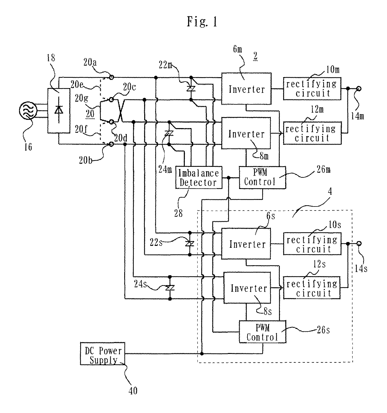
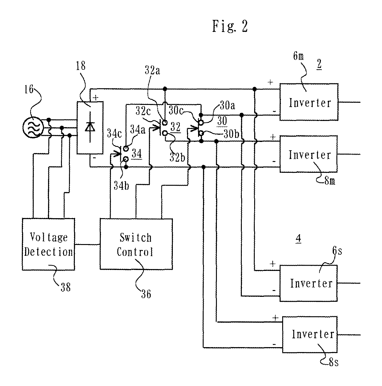
[0012]A power supply apparatus according to one embodiment of the present invention may be used with a plasma welding machine and a plasma cutting machine, for example. As shown in FIG. 1, the power supply apparatus has a main unit 2 for supplying power to a plasma load, for example, and a subsidiary unit 4 for generating a plasma arc, for example. The main and subsidiary units 2 and 4 of the power supply apparatus being described are arranged to be operable from either one of two commercial AC voltages having different values, e.g. 100 V and 200 V commercial AC voltages.

[0013]The main unit 2 includes two inverters 6m and 8m which convert DC voltage applied thereto into AC voltages and output the resultant AC voltages. The inverters 6m and 8m have the same output capacity. The outputs of the inverters 6m and 8m are converted into DC by rectifying means, for example, rectifying circuits 10m and 12m, respectively, and combined into one output. The combined output is developed at an ou...


PUM

PropertyMeasurementUnit
AC voltagesaaaaaaaaaa
DC voltageaaaaaaaaaa

Abstract

A main unit 2 and a subsidiary unit 4 include two inverters 6m, 8m and 6s, 8s, and PWM control circuits 26m, 26s, respectively. A changeover switch 20 operates to simultaneously connect the inputs of the two inverters of the main unit 2 and the inputs of the two inverters of the subsidiary unit 4 in series or in parallel. An imbalance detecting circuit 28 detects imbalance in the input voltages to the two inverters of the main unit 2, and provides the detection result to the PWM control circuits 26m and 26s. The PWM control circuit 26m controls the inverters 6m and 8m of the main unit 2 in accordance with the detection result supplied from the imbalance detecting circuit 26m, and the PWM control circuit 26s controls the subsidiary unit 4 in accordance with the detection result supplied from the imbalance detecting circuit 26m. The input current to the main unit 2 is larger than the input current to the subsidiary unit 4.

Description

TECHNICAL FIELD[0001]This invention relates to a power supply apparatus and, more particularly, to a power supply apparatus which is supplied with one of two selectable voltages of different magnitudes and operates in a manner suitable for the selected supply voltage.BACKGROUND ART[0002]An example of the above-stated type of power supply apparatus is disclosed in Japanese Patent No. 4758234 B. The power supply apparatus of Japanese Patent No. 4758234 B is arranged to be supplied with a selected one of commercial AC voltages of, for example, 200 V and 400 V. The power supply apparatus includes two inverters. When the voltage of larger value, 400 V, is supplied to the power supply apparatus, a DC voltage resulting from conversion of the supplied 400 V AC voltage is applied to a series connection of the two inverters, and, when the voltage of smaller value, 200 V, is supplied, a DC voltage resulting from conversion of the supplied 200 V AC voltage is applied to a parallel connection of...

Claims


Application Information

Patent Timeline
Patent Type & Authority Patents(United States)
IPC IPC(8): H02M7/44B23K10/00H02M3/158H02M7/10H02M7/02H02M7/08H02M1/00H02M7/48
CPCB23K10/006H02M7/44H02M7/10H02M2003/1586H02M7/02H02M7/08H02M2001/0058H02M2007/4811H02M1/10H02M1/008H02M1/007Y02B70/10H02M1/0058H02M3/1586H02M7/4811
Inventor SASO, HIROSHIMORIMOTO, TAKESHI
Owner SANSHA ELECTRIC MFG
Why Eureka
Try Eureka