Anatomical robot

a robot and anatomical technology, applied in the field of robots, can solve the problems of sacrificing a great deal of manipulation functionality, affecting the operation of the robot, so as to achieve the effect of eliminating rigor mortis, reducing the number of robots, and reengineering the work environmen

Active Publication Date: 2019-07-30
SMALLRIDGE BRAD
View PDF14 Cites 0 Cited by
  • Summary
  • Abstract
  • Description
  • Claims
  • Application Information

AI Technical Summary

Benefits of technology

[0014]Another objective of this invention is to provide a new and novel approach to the design of anatomical robots. Over-simplistic conventional designs usually result in limited range, awkward motions, or other disadvantages. For example, the palm of a human is not an inflexible shell. The bones inside a human palm, carpals and metacarpals, give the human palm a degree of flexibility useful for grasping many hand tools as well as a variety of other functions. To model the human palm with an inflexible shell, which is done in the majority of anthropomorphic robot designs, sacrifices a great deal of manipulation functionality.
[0016]But if human form is followed, there are certain advantages that could be useful. An exact anatomical robot, for one example that should not be considered limiting, can be used in the medical field in place of cadavers. This offers the advantages of an ample supply of inexpensive artificial subjects, no smells or toxicity associated with embalming fluids or the thawing of frozen body parts, no predominance of older, frail, or sickly subjects, no lack of cadavers and no rigor mortis. Additionally, certain features of the anatomical robot, could be highlighted with colors, or embossed labels, for instructive purposes.
[0017]A robot built with human form also has advantages of performing tasks more like a human would perform tasks. If each motion of an anatomical robot is fundamentally the same as human motion, there is no human motion that the anatomical robot cannot do. The reengineering of work environment, motion planning, protective clothing, and tooling is eliminated.

Problems solved by technology

Over-simplistic conventional designs usually result in limited range, awkward motions, or other disadvantages.
To model the human palm with an inflexible shell, which is done in the majority of anthropomorphic robot designs, sacrifices a great deal of manipulation functionality.

Method used


Image

  • Anatomical robot
  • Anatomical robot
  • Anatomical robot

Examples


Embodiment Construction

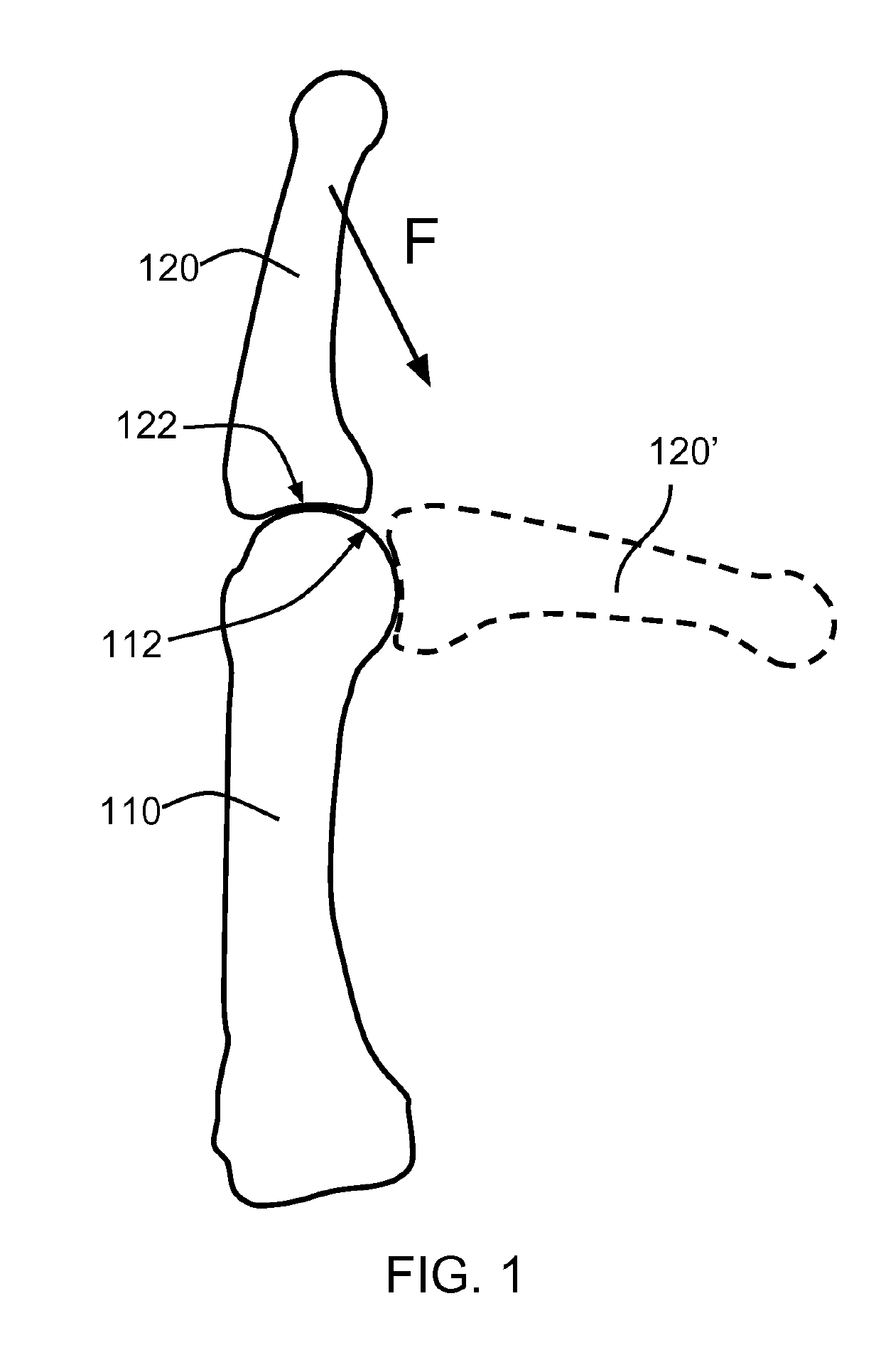
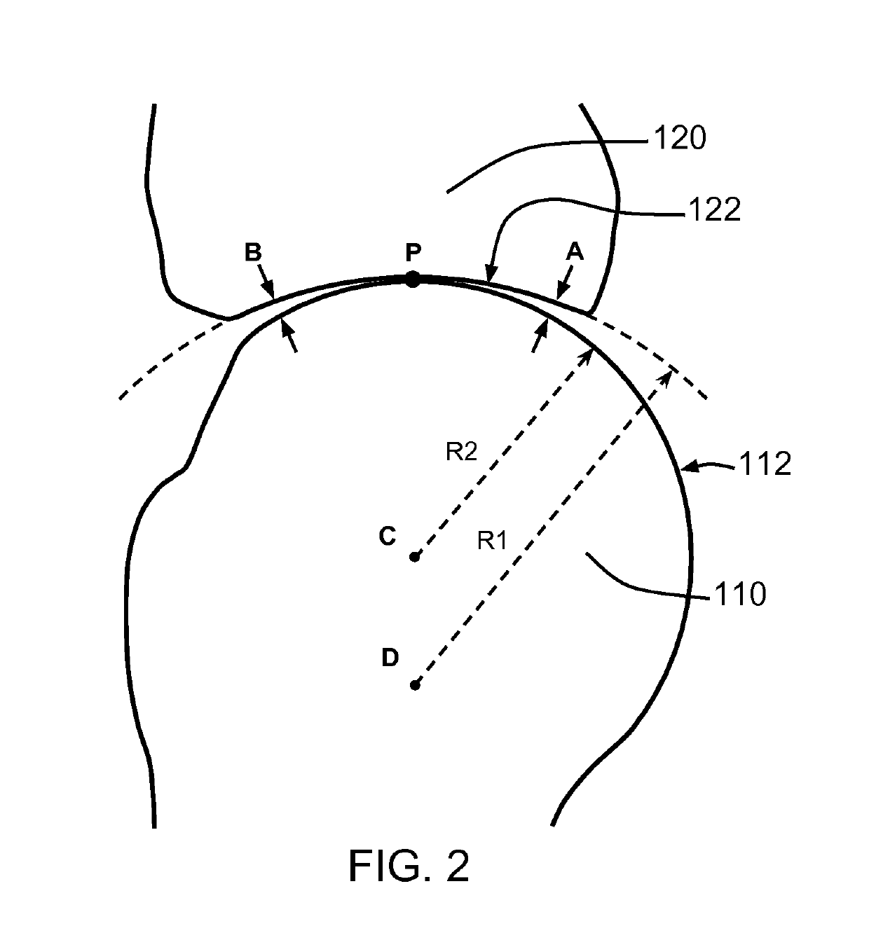
[0038]An important and defining part of an anatomical robot are the anatomical robot joints. Analogous to biological joints that connect and allow bones to move, anatomical robot joints allow movement of the structures of an anatomical robot. There are two important components to any one anatomical robot joint, the contacting surfaces between two structures and the flexible bands that hold the two surfaces together. Flexible bands couple two structures together but still allow motion of one structure relative the other structure.

[0039]Also important to an anatomical robot joint is that when two contacting surfaces are coupled together, one surface is a concave shape and the other surface is a convex shape. The two surfaces are further defined as single lobe, double lobe, or saddle shaped.

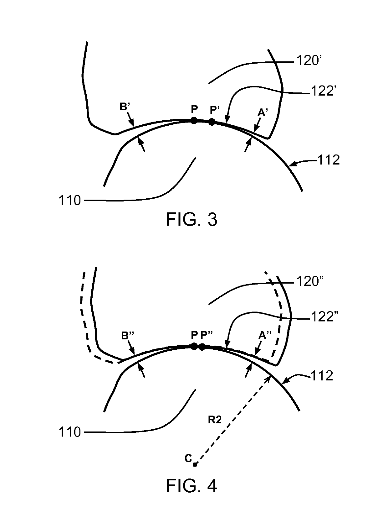
[0040]There are three basic types of motion, as defined in this invention, that can occur in an anatomical robot joint. These types of motion are rocking, slipping, and twisting. Rocking type of mot...


PUM


Abstract

A robot having anatomical robot joints with convex surfaces significantly less in average overall curvature than their corresponding concave surfaces; having single lobe, double lobe, or saddle shapes; and held together by flexible bands that allow rocking, slipping, and twisting types of motion.

Description

CROSS-REFERENCE TO RELATED APPLICATIONS[0001]Not applicable.FEDERALLY SPONSORED RESEARCH OR DEVELOPMENT[0002]Not applicable.BACKGROUND OF THE INVENTION[0003]1. Field of the Invention[0004]This invention relates to the field of robotics. There are many types of robots. Some remote control or autonomous boats, submarines, vehicles, aircraft, or missiles are considered robots. Some computer numerically controlled automated mills, lathes, or other machinery are considered robots. And sometimes a simple non-moving electronic device, modem, computer, or data server is called a robot. This invention is specifically about robots, either whole or part of a whole, that have at least one articulated joint, including, but not limited to, SCARA robots, Stewart platforms, pick-and-place robots, animatronic robots, legged robots, armed robots, anthropomorphic robots, animal robots, fish robots, insect robots, motion controlled camera jibs and cranes, space exploration robots, firefighting robots, ...

Claims


Application Information

Patent Timeline
Patent Type & Authority Patents(United States)
IPC IPC(8): B25J17/02B25J15/00B25J18/04
CPCB25J17/0275B25J18/04B25J15/0009B25J17/00
Inventor SMALLRIDGE, BRAD
Owner SMALLRIDGE BRAD
Why Eureka
Try Eureka