
Man-made vitreous fibres

a technology vitreous fibres, which is applied in the field of man-made vitreous fibres, can solve the problems of increasing the volume of mmvf substrates, increasing the space required for technical insulation, and increasing so as to avoid collapsing of buildings, and reduce the cost of technical insulation

Active Publication Date: 2019-08-06
ROCKWOOL AS
View PDF21 Cites 0 Cited by
  • Summary
  • Abstract
  • Description
  • Claims
  • Application Information

AI Technical Summary

Benefits of technology

[0173]MMVF substrates according to the present invention are considered to be softer and more pleasant to touch than conventional MMVF products and are thus more skin friendly. This is thought to be due at least partly to the low fibre diameter of the MMVF and the low levels of shot present. It is a further advantage of the present invention that the MMVF substrates are easier to handle than conventional MMVF substrates.
[0174]The thermal conductivity, expressed as lambda value, of the MMVF substrates of the invention is lower than conventional products and this is demonstrated in Example 3. The lambda value of the MMVF substrates is particularly low at high temperatures, such as above 300° C., compared to conventional MMVF substrates. This means that the MMVF substrates of the present invention have particular utility in areas where it is important to have a low lambda value in environments where the temperature is above 300° C., such as for use as (a) technical insulation or (b) fire protection in an industrial or marine environment. In particular, the MMVF of the present invention may be used as a marine batt, a marine slab, a marine lamella mat, a marine wired mat, a marine pipe section or a marine firebatt.
[0175]Further, the invention relates to the use of an MMVF substrate as (a) technical insulation or (b) fire protection at a temperature of at least 300° C. Products for use above 300° C. include products for thermal insulation of technical installations, e.g. pipe sections, wired mats for pipes, boilers, vessels, tanks, chimneys, and products for fire protection, such as fire slabs, fire door inlays, insulation for ventilation ducts, etc. to inhibit the spread of fire for a specified period or e.g. to protect columns against the heat of a fire for some time to avoid collapsing of a building.
[0176]The MMVF substrate preferably has an ignition loss of up to 2 wt %, such as 0.5 to 2.0 wt %, preferably 0.8 to 1.5 wt %. MMVF substrates with this ignition loss preferably have a density in the range of 60 kg / m3 to 150 kg / m3, more preferably 80 to 130 kg / m3. Such MMVF substrates have particular utility in high temperature environments, such as 100 to 650° C., and as fire protection. The Ignition Loss of an MMVF substrate is a measure of the amount of organic material such as binder present in the MMVF substrate. The ignition loss of a dry sample may be measured e.g. by heating the MMVF to 590° C. for at least 20 minutes and weighing the sample before and after heating to determine the loss of material.
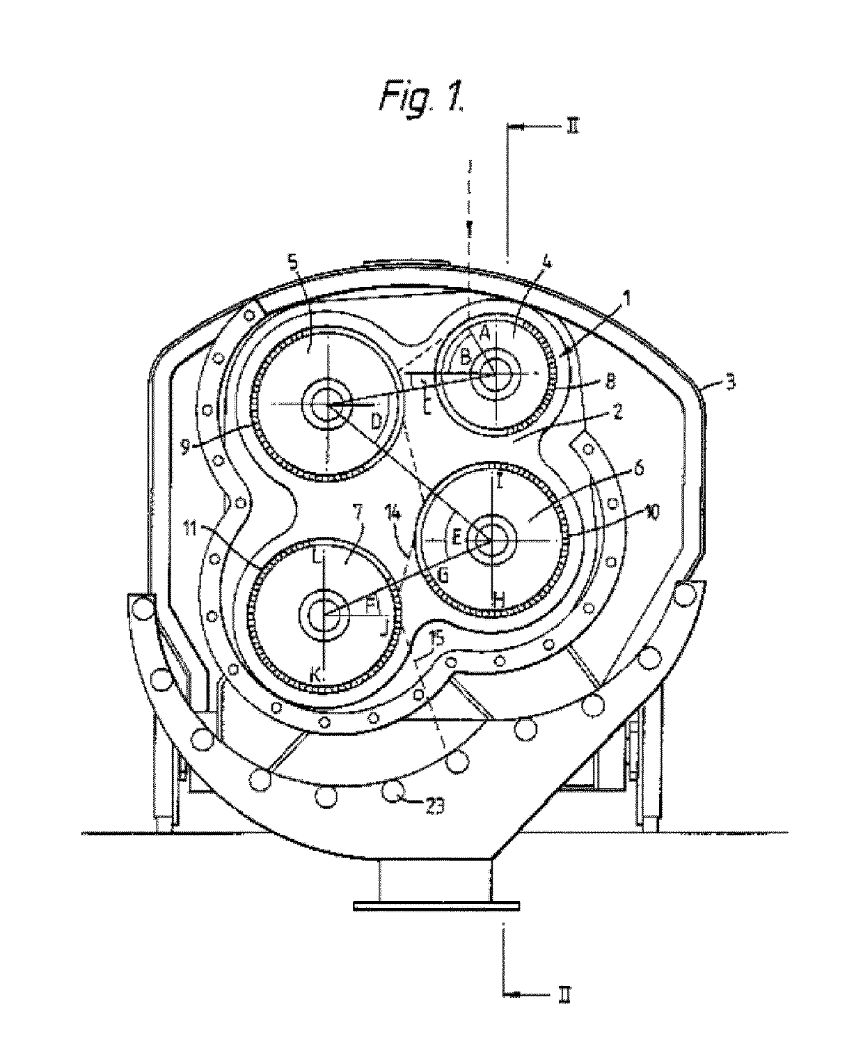
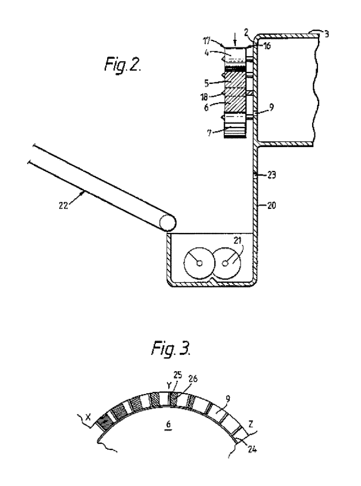
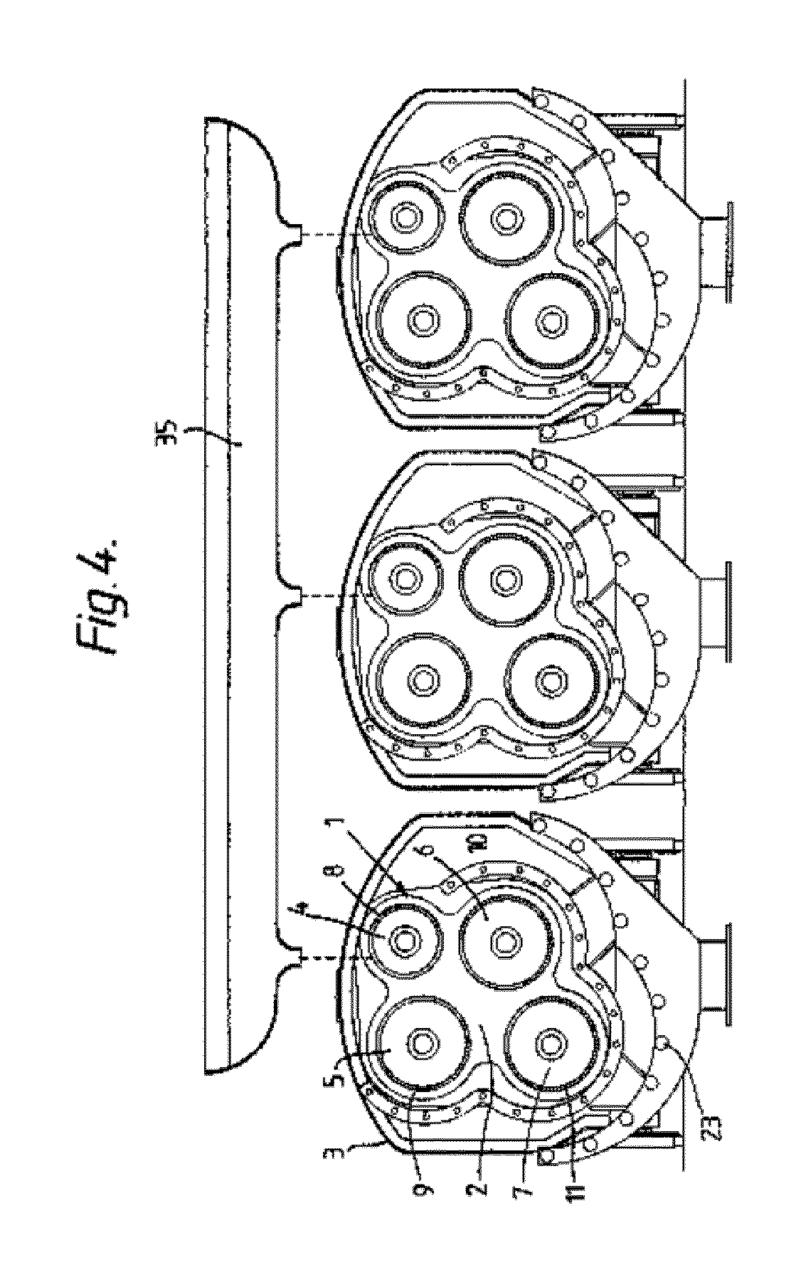
[0177]The invention is illustrated by reference to the accompanying drawings in which:
[0178]FIG. 1 is a front view of a set of rotors assembled for use in the method according to the invention;

Problems solved by technology

Increasing the volume of the MMVF substrate however is undesirable as it increases the cost of the technical insulation, increases the space required for the technical insulation and increases the environmental impact of producing the technical insulation.

Method used


Image

  • Man-made vitreous fibres
  • Man-made vitreous fibres
  • Man-made vitreous fibres

Examples


example 1

[0203]The air flow resistivity of four MMVF substrates according to the present invention (Examples A to D) was compared to the air flow resistivity of five MMVF substrates not of the invention (Comparative Examples A to E). Each MMVF substrate contained approximately 1 wt % binder. The MMVF substrates of Examples A to D were made by the method of manufacture of the present invention and the MMVF were in accordance with the present invention. The MMVF substrates of Comparative Examples A to E were made by a different method of manufacture and the MMVF were conventional MMVF.

[0204]The MMVF of Examples A to D were made on a spinner equipped with four rotors. The first rotor had a diameter of 210 mm and was driven at approximately 5,000 rpm (acceleration field 29 km / s2). The second to fourth rotor had a diameter of 280 mm and were driven at approximately 12,000 rpm (acceleration field 225 km / s2).

[0205]The MMVF of Comparative Examples A to E were made on a conventional spinner equipped ...

example 2

[0208]The diameter of a sample of MMVF of the present invention was compared to a sample of conventional MMVF. The MMVF of the present invention were made as described for Examples A to D. The conventional MMVF were made as described for Comparative Examples A to E. FIG. 5 shows that the spread of fibre diameters is much smaller for MMVF of the present invention than for the conventional wool. The range of variation is defined here as the 84% quantile minus the 16% quantile (+ / −1× standard deviation for the fibre diameter−(logarithmic normal distribution)). This means that the probability is 68% of finding a given fibre diameter in the defined region. As shown in FIG. 5, there is far less variation in fibre diameter of MMVF of the present invention, than of conventional wool. In specific tests the range of variation for MMVF of the present invention was found to be 2.3-2.4 μm at a median fibre diameter of 1.9 μm to 2.2 μm, where the range of variation for MMVF of conventional wool w...

example 3

[0209]The lambda values of four MMVF substrates of the present invention (Examples E to H) were compared to those of four MMVF substrates not of the invention (Comparative Examples F to I). The MMVF of Examples E to H were made as described for Examples A to D. The conventional MMVF of Comparative Examples F to I were made as described for Comparative Examples A to E. Lambda was measured in accordance with EN 12667. The density was measured in accordance with EN 1602. Each MMVF substrate contained approximately 1 wt % binder. The MMVF substrates of Examples E to H were made by the method of manufacture of the present invention and the MMVF were in accordance with the present invention. The MMVF in the MMVF substrates of Comparative Examples F to I were made by a different method of manufacture and the MMVF were convention MMVF. The density of each product is shown below. The lower the lambda value, the greater the resistance of the MMVF substrate to heat. As shown in Table 2 below, ...


PUM

PropertyMeasurementUnit
diameteraaaaaaaaaa
weight %aaaaaaaaaa
angleaaaaaaaaaa

Abstract

The invention provides a method of manufacture of man-made vitreous fibers (MMVF) comprising: providing a fiberizing apparatus, wherein the fiberizing apparatus comprises: a set of at least three rotors each mounted for rotation about a different substantially horizontal axis; wherein each rotor has a driving means; rotating the rotors; wherein the first rotor rotates to give an acceleration field of from 25 to 60 km / s2 and the second and third rotors each rotate to give an acceleration field of at least 125 km / s2, providing a mineral melt, wherein the melt has a composition comprising the following, expressed by wt of oxides: SiO2 in an amount of from 33 to 45 wt %, Al2O3 in an amount of from 16 to 24 wt %, an amount of K2O and / or Na2O, an amount of CaO and / or MgO, wherein the ratio of the amount of Al2O3 to the amount of SiO2 is in the range 0.34-0.73, wherein the ratio of the total amount of K2O and Na2O, to the total amount of CaO and MgO, is less than 1; pouring the melt on to the periphery of the first rotor; wherein melt poured on to the periphery of the first rotor in the set is thrown on to the periphery of the subsequent rotors in turn and fibers are thrown off the rotors; and collecting the fibers that are formed. Man-made vitreous fibers (MMVF) can thus be formed having a median length of 100 to 300 μm, a median diameter of not more than 2.5 μm, and wherein the ratio of the median fiber length to median fiber diameter is 25 to 500.

Description

RELATED APPLICATIONS[0001]The present application is a U.S. National Stage under 35 USC 371 patent application, claiming priority to Serial No. PCT / EP2014 / 072200, filed on Oct. 16, 2014, which claims priority from EP 13188945.3, filed on Oct. 16, 2013, both of which are incorporated herein by reference.TECHNICAL FIELD[0002]The present invention relates to man-made vitreous fibres (MMVF), a man-made vitreous fibre substrate, use of a man-made vitreous fibre substrate, a method of manufacture of man-made vitreous fibres and an apparatus for formation of man-made vitreous fibres.BACKGROUND[0003]It is known to use MMVF as an insulation material to provide acoustic or heat insulation. The MMVF are usually formed into an MMVF substrate which is formed as a bonded web comprising the MMVF and a cured binder composition. The requirements for an MMVF substrate to withstand heat vary depending on the ultimate use of the MMVF substrate. For example, in marine and industrial applications, the MM...

Claims


Application Information

Patent Timeline
Patent Type & Authority Patents(United States)
IPC IPC(8): C03B37/05C03C3/062D21H13/40C03C13/06C09K21/02C03C13/00C03C3/085
CPCC03B37/055C03C3/062C03C3/085C03C13/06C09K21/02D21H13/40C03C13/00Y02P40/57
Inventor HANSEN, LARS ERIKSOLVANG, METTEDEHN, SUSANNE
Owner ROCKWOOL AS
Learn More