Device for holding and bringing into electrical contact conductors

a technology for electrical contact conductors and devices, which is applied in the direction of coupling contact members, electrical apparatus, connections, etc., can solve the problems of inability the thickness of intermediate conductive parts cannot be reduced for gaining space, and it is difficult to reduce the bulk of such junction blocks. , to achieve the effect of reducing the thickness, limiting the thickness of intermediate conductive parts, and reducing the thickness

Active Publication Date: 2019-08-06
TYCO ELECTRONICS LOGISTICS AG (CH)
View PDF7 Cites 0 Cited by
  • Summary
  • Abstract
  • Description
  • Claims
  • Application Information

AI Technical Summary

Benefits of technology

[0015]Hence, this arrangement allows designing a compact junction block, two conductors may be disposed in the proximity of each other and not at two distant locations.
[0056]Comparatively, according to the state of the art, two electrical conductors are brought into electrical contact via a bar having a current circulation section transverse to the main direction of extension of said bar. In this case, reducing the thickness, that is to say the dimension transverse to the direction of extension of the bar results in reducing the current passage section.

Problems solved by technology

Nonetheless, the fact of using on the one hand a conductive bar extending according to a longitudinal direction and on the other hand two distant retaining elements arranged to hold the conductors away from each other according to the longitudinal direction, imposes some constraints in terms of construction.
In particular, the length of the bar according to the longitudinal direction imposes the longitudinal dimension of the junction block which thus cannot be reduced for gaining space.
In these conditions, it seems to be difficult to reduce the bulk of such junction blocks.

Method used


Image

  • Device for holding and bringing into electrical contact conductors
  • Device for holding and bringing into electrical contact conductors
  • Device for holding and bringing into electrical contact conductors

Examples


Embodiment Construction

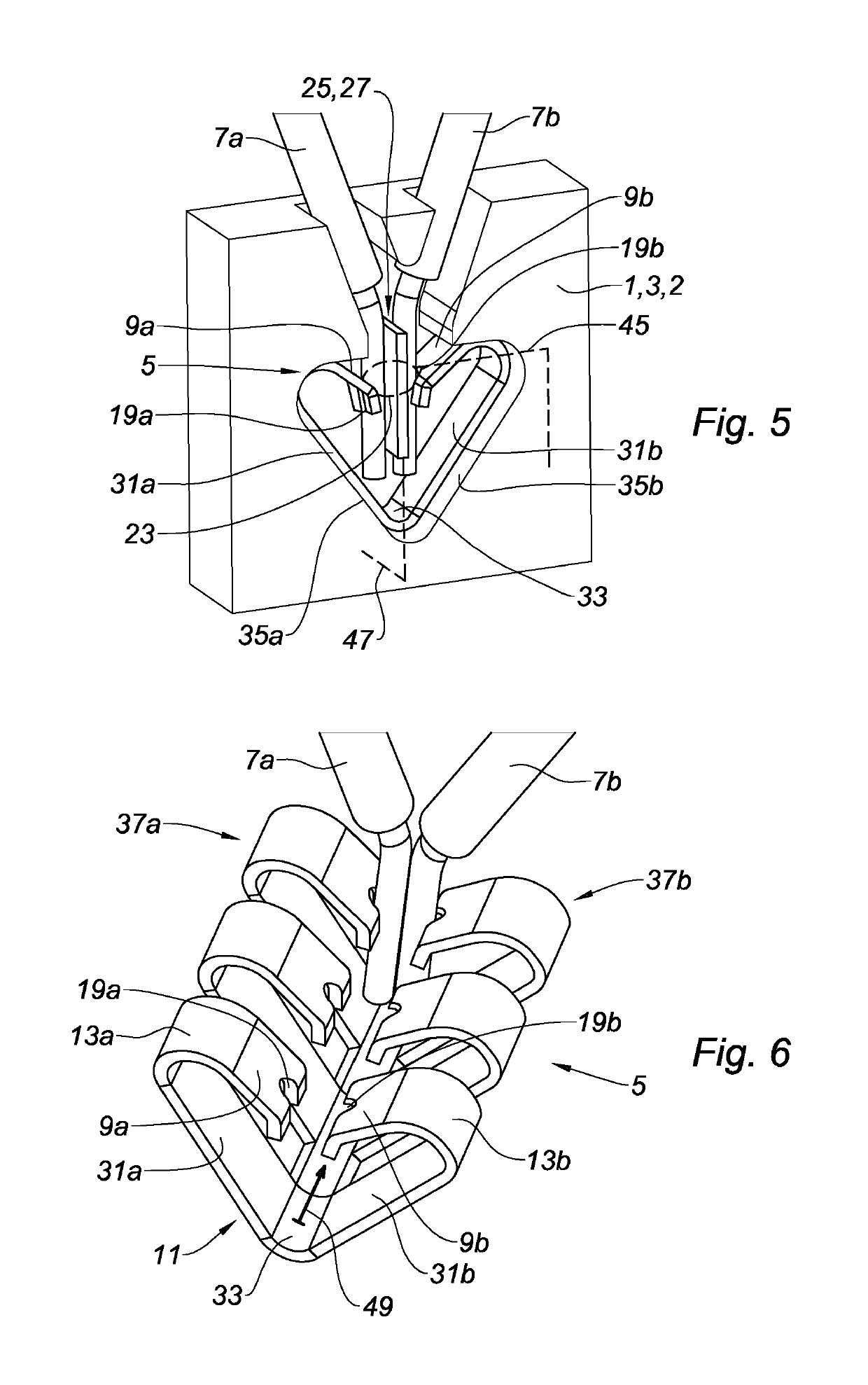
[0079]As illustrated in FIG. 5, an electrical apparatus 1, in particular a junction block 2 comprises an insulating body 3 and a device 5 for holding in position and bringing into electrical contact a first electrical conductor 7a and a second electrical conductor 7b.

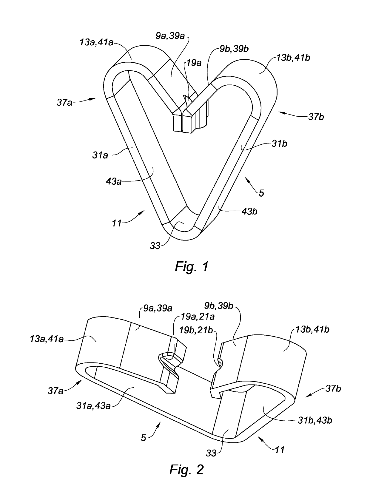
[0080]As also illustrated in FIGS. 1 to 4, the device 5 for holding in position and bringing into electrical contact comprises a first retaining element 9a, a second retaining element 9b and a connecting element 11.

[0081]The connecting element 11 comprises a first flexible portion 13a and a second flexible portion 13b, each adjacent and secured respectively to the first retaining element 9a and to the second retaining element 9b.

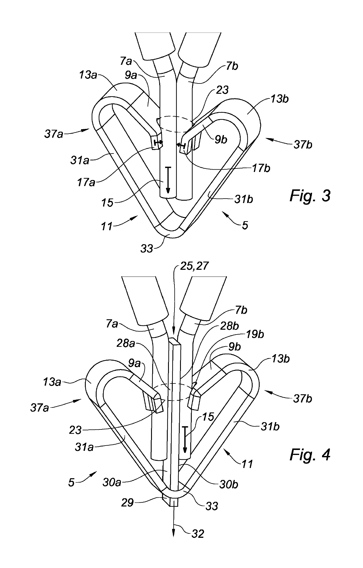
[0082]This flexibility enables the independent displacement of each retaining element 9a, 9b relative to the connecting element 11. In FIGS. 3 to 5, each retaining element 9a, 9b is disposed at a retaining position in which the corresponding electrical conductor 7a, 7b extending according to a...


PUM


Abstract

The invention relates to a device for holding in position and placing in electrical contact (5) for a connection terminal of an electrical apparatus (1), arranged to hold in position and place in electrical contact at least two electrical conductors (7a, 7b), the device (5) comprising: a first retaining element (9a) having a first engagement portion (19a) arranged to engage, in a retailing position, with a first electrical conductor (7a); a second retaining element (9b) having a second engagement portion (19b) arranged to engage, in a retaining position, with a second electrical conductor (7b); and a clamping point (23) defined at least partially in the retaining position by the first engagement portion (19a) and the second engagement portion (19b).

Description

CROSS REFERENCE TO RELATED APPLICATIONS[0001]This application is a National Stage of PCT Application No. PCT / EP2015 / 074851 filed on Oct. 27, 2015, the contents of which is incorporated herein by reference thereto.TECHNICAL FIELD[0002]The present invention concerns a device for holding in position and bringing into electrical contact at least two electrical conductors.BACKGROUND[0003]It is known to use electrical apparatuses such as junction blocks or terminal blocks to bring into electrical contact and hold in position two conductors. For this purpose, a junction block may comprise a conductive bar against which the two conductors are held in position.[0004]The conductors may be held in contact position with the conductive bar by using one retaining element per conductor such as for example a leaf spring. Thus, the conductors are disposed away from each other and each is held in position against the bar.[0005]This arrangement is satisfactory in that each conductor can be set in posi...

Claims


Application Information

Patent Timeline
Patent Type & Authority Patents(United States)
IPC IPC(8): H01R13/15H01R4/48H01R9/26
CPCH01R4/4827H01R9/2616H01R4/4818H01R4/4845H01R4/48275H01R4/48455H01R4/48185
Inventor CHAILLET, ALEXANDREFRANCE, PHILIPPE
Owner TYCO ELECTRONICS LOGISTICS AG (CH)
Why Eureka
Try Eureka