Microstructure arrangement for gripping low coefficient of friction materials

a low friction material and microstructure technology, applied in the direction of gripping heads, manipulators, manufacturing tools, etc., can solve the problems of low cof material gripping, low gripping force, delicate operations, cumbersome current solutions, etc., and achieve the effect of improving grip

Inactive Publication Date: 2019-08-13
HOOWAKI
View PDF9 Cites 17 Cited by
  • Summary
  • Abstract
  • Description
  • Claims
  • Application Information

AI Technical Summary

Benefits of technology

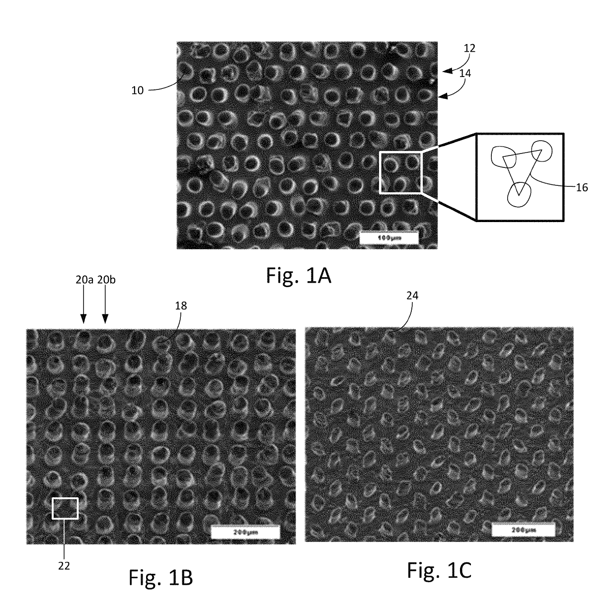
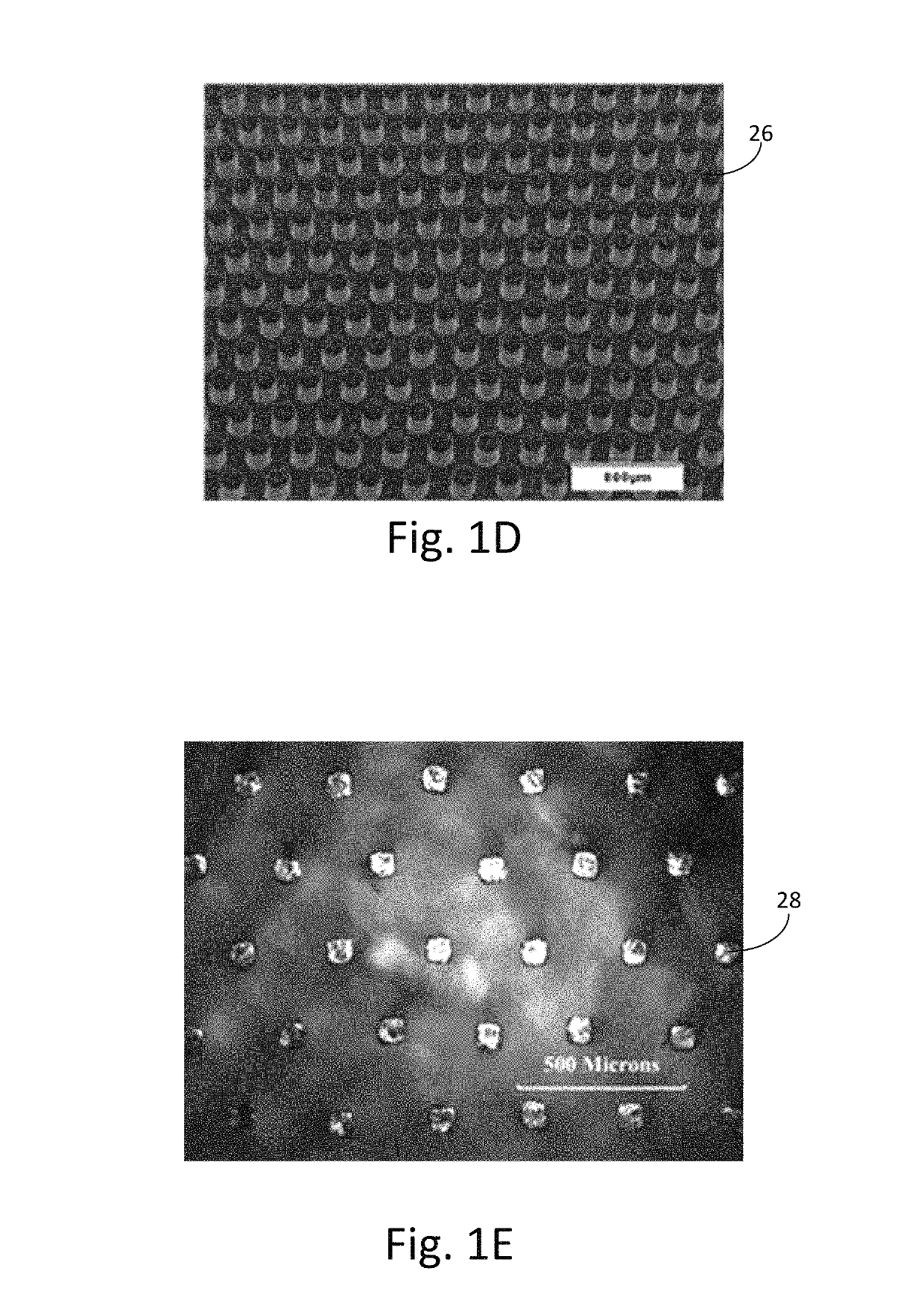
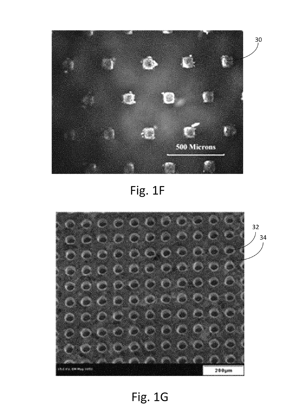
[0004]Gripping, moving and manipulating devices made of low COF polymer by devices with a gripping pad is improved by forming a pattern of microstructure features according to the present invention on at least one surface of the gripping pad. Coefficient of friction greater than 0.90 was achieved using patterns of microstructure arrays covering the gripping pad and molded in a material with a Young's modulus greater than the Young's modulus of the material being gripped. Microstructures having a width greater than 2 microns and less than 500 microns were the most effective at providing grip on low COF materials such as PTFE. Some of the most effective gripping occurred when contact is less than about 25% and greater than about 0.25%. The microstructure features can further consist of one array stacked on another array of larger microstructure features, which further improves grip.

Problems solved by technology

However, these low COF items must also be gripped during manufacturing, or during use, or during disassembly and disposal.
Current solutions for gripping low COF materials are cumbersome and require mechanical methods such as holes, slots or threads; or they accept low levels of grip force and delicate operations.
It is also difficult to grip low COF rubbery polymers such as silicone rubber or human skin.
Previous attempts to address these problems include unsatisfactory use of additives that results in “sticky” surfaces or use adhesives which are undesirable as they can be too sticky, create unnecessarily rough surfaces, and can cause pain to the user.

Method used


Image

  • Microstructure arrangement for gripping low coefficient of friction materials
  • Microstructure arrangement for gripping low coefficient of friction materials
  • Microstructure arrangement for gripping low coefficient of friction materials

Examples


Embodiment Construction

[0022]With reference to the drawings, the invention will now be described in more detail. Unless defined otherwise, all technical and scientific terms used herein have the same meaning as commonly understood to one of ordinary skill in the art to which the presently disclosed subject matter belongs. Although any methods, devices, and materials similar or equivalent to those described herein can be used in the practice or testing of the presently disclosed subject matter, representative methods, devices, and materials are herein described.

[0023]Unless specifically stated, terms and phrases used in this document, and variations thereof, unless otherwise expressly stated, should be construed as open ended as opposed to limiting. Likewise, a group of items linked with the conjunction “and” should not be read as requiring that each and every one of those items be present in the grouping, but rather should be read as “and / or” unless expressly stated otherwise. Similarly, a group of items ...


PUM

PropertyMeasurementUnit
heightaaaaaaaaaa
heightaaaaaaaaaa
friction testing methodaaaaaaaaaa

Abstract

A microstructure arrangement for gripping low coefficient material comprising: a substrate disposed on a gripping surface; a set of pillars disposed on the substrate; and, wherein the set of pillars have the physical property of a grip force in excess of 50.0N with a contact area of 25% or less as determined by the friction testing method. A first set of pillars can be disposed on the substrate having a cross section area in the range of 100 μm2 to 160,000 μm2, height relative to the substrate in the range of 10 μm to 400 μm, and a pitch determined from the center of the pillars, in the range of 20 μm to 1000 μm; and a secondary set of pillars disposed on the first set of pillars having a cross section area less than that of the pillars in the first set of pillars.

Description

BACKGROUND OF THE INVENTION[0001]The present invention relates to microstructure patterns, and more particularly, to a gripping surface having a microstructure pattern adapted for improving grip on low coefficient of friction materials.[0002]Polymer materials with low coefficient of friction (COF), such as PTFE, HDPE, nylon or POM, are manufactured into devices to allow easy sliding of devices with or without a lubricant being present. Typical examples include a PTFE shaft seal sliding against a polycarbonate housing; a nylon covered vascular catheter sliding through a polypropylene introducer tube, or a PTFE coated guide wire sliding inside a PTFE lined vascular catheter. However, these low COF items must also be gripped during manufacturing, or during use, or during disassembly and disposal. Particularly during manufacturing and use, gripping the item must be done carefully to prevent causing damage or degradation, such as creating scratches or generating contaminating particles. ...

Claims


Application Information

Patent Timeline
Patent Type & Authority Patents(United States)
IPC IPC(8): B25J15/00B22F5/00B22F7/08
CPCB25J15/0028B22F7/08B22F5/00B22F2005/005
Inventor HULSEMAN, RALPH A.MCPHERSON, CAMERON L.RAVIKUMAR, NAKUL
Owner HOOWAKI
Why Eureka
Try Eureka