Surgical linear stapler

a linear stapler and surgical technology, applied in the field of surgical staplers, can solve the problems of difficult to correctly examine whether cancer cells are remained in the cutting margin, and achieve the effect of stably and conveniently obtaining tissu

Active Publication Date: 2019-08-20
MEDI TULIP
View PDF62 Cites 616 Cited by
  • Summary
  • Abstract
  • Description
  • Claims
  • Application Information

AI Technical Summary

Benefits of technology

[0006]Accordingly, the present invention is conceived to solve the foregoing problems, and an aspect of the present invention is to provide a surgical linear stapler which can stably and conveniently obtain tissue for pathological examination, which is not damaged by a staple, while stapling and cutting a surgical site.

Problems solved by technology

However, biological tissue adjacent to a section obtained for frozen section tissue examination from a surgical site removed after being stapled and cut by a conventional stapler is damaged by a staple, and it is therefore difficult to correctly examine whether a cancer cell is remained in a cutting margin.

Method used


Image

  • Surgical linear stapler
  • Surgical linear stapler
  • Surgical linear stapler

Examples


first embodiment

[0019]A surgical linear stapler according to the present invention for obtaining tissue for pathological examination will be described with reference to FIG. 1 to FIG. 4.

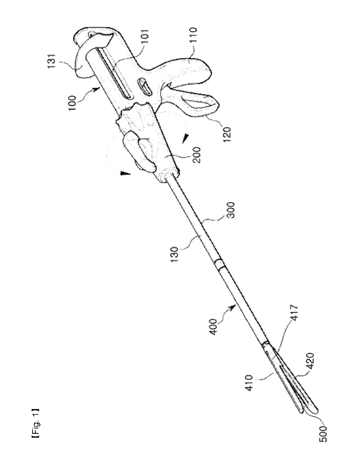
[0020]Referring to FIG. 1 to FIG. 4, the surgical linear stapler includes a main body 100, a rotary head 200, an extension shaft 300, a stapling shaft 400, a staple cartridge 500 and a cutter 600.

[0021]The main body 100 includes a support grip 110 to be gripped by a user, a control grip 120 arranged in front of the support grip 110 and hinge-coupled to the support grip 110, and the stroke bar 130.

[0022]The stroke bar 130 is interlocked with the control grip 120 while penetrating the standing extension shaft 300 and the rotary head 200 and also connects with a pull grip 131.

[0023]The stroke bar 130 moves forward when the control grip 120 is controlled, and moves backward when a user pulls the pull grip 131 backward.

[0024]The pull grip 131 moves in the lengthwise direction of the main body 100 along guide elongated ho...

second embodiment

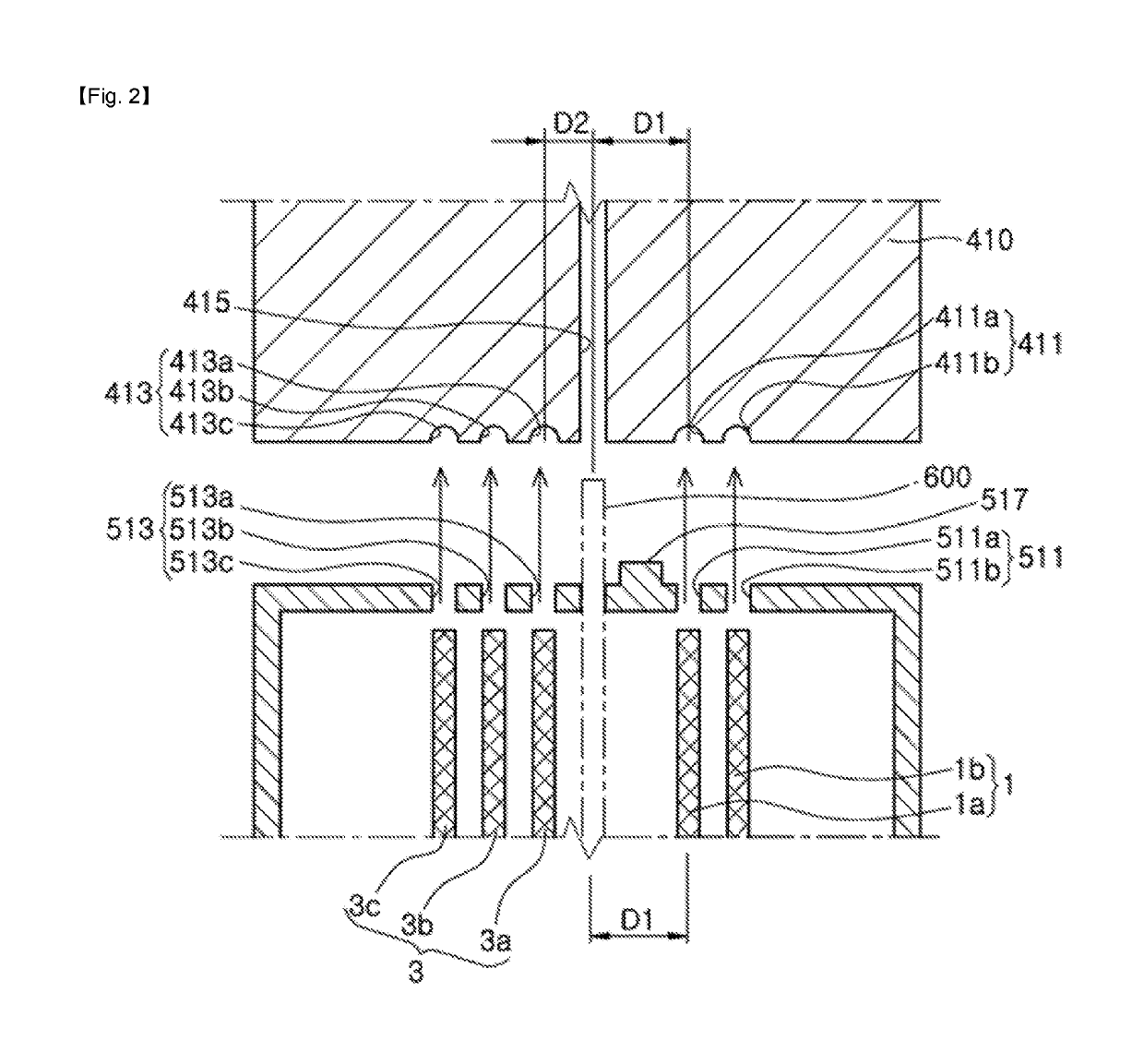
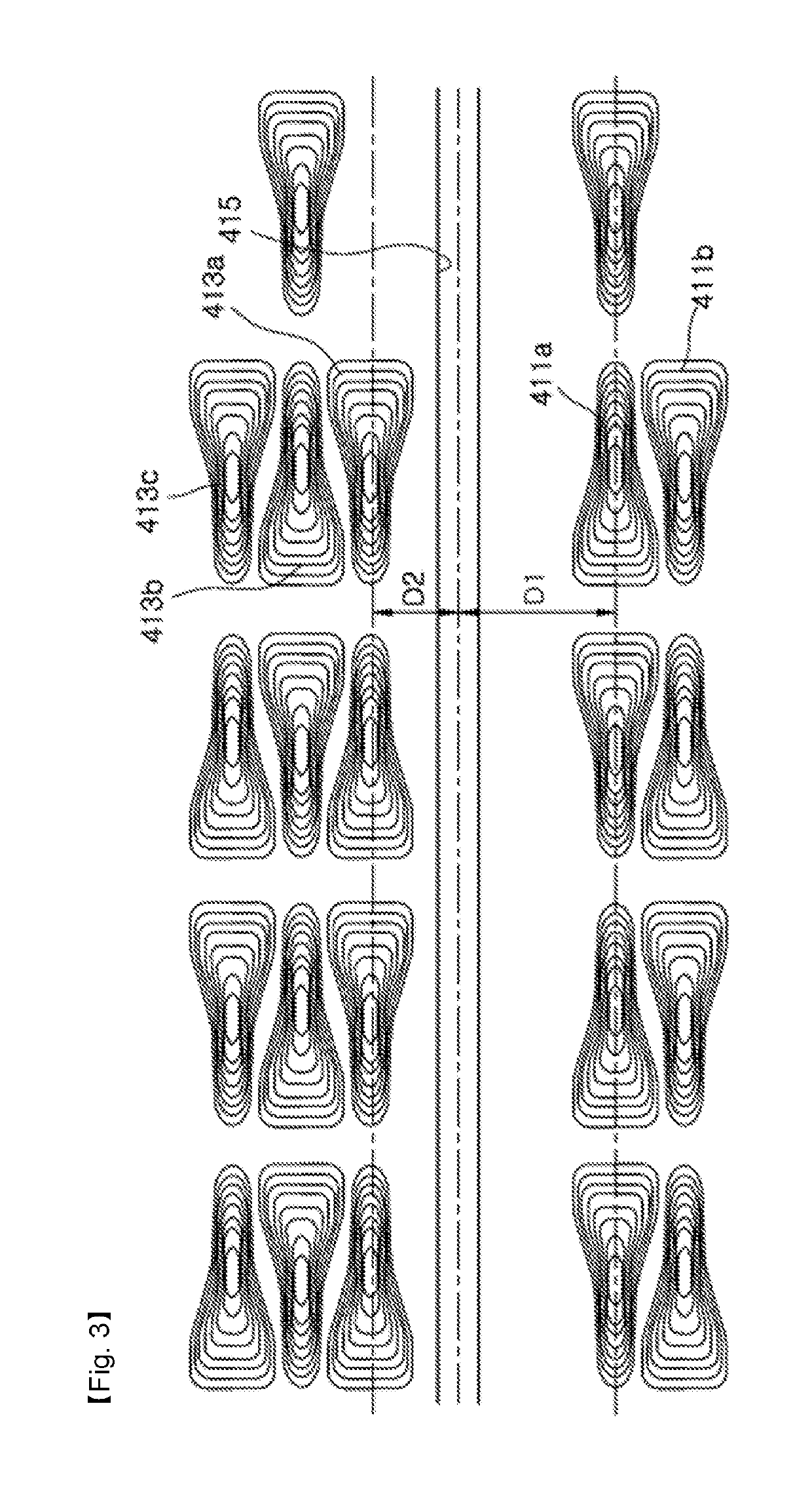
[0065]Below, cross-sections of the staple cartridge and the anvil provided in the surgical linear stapler according to the present invention will be described with reference to FIG. 5.

[0066]The elements of the surgical linear stapler in the second embodiment are similar to those of the surgical stapler according to the first embodiment. However, an anvil 710 provided in the surgical linear stapler according to the second embodiment is different from the anvil provided in the surgical linear stapler according to the first embodiment.

[0067]Specifically, the anvil 710 is formed with a first cutter guide 715, a right anvil groove 711, a left anvil groove 713 arranged in the leftward direction, in which the right anvil groove 711 includes a first right anvil groove 711a and a second right anvil groove 711b, and the left anvil groove 713 includes a first left anvil groove 713a, a second left anvil groove 713b and a third left anvil groove 713c.

[0068]To more firmly hold an area, which is ...

third embodiment

[0073]Below, cross-sections of the staple cartridge and the anvil provided in the surgical linear stapler according to the present invention will be described with reference to FIG. 6.

[0074]The elements of the surgical linear stapler in the third embodiment are similar to those of the surgical stapler according to the first embodiment. However, an anvil 810 provided in the surgical linear stapler according to the third embodiment is different from the anvil provided in the surgical linear stapler according to the first embodiment.

[0075]Specifically, the anvil 810 is formed with a first cutter guide 815, a right anvil groove 811, and a left anvil groove 813 arranged in the leftward direction, in which the right anvil groove 811 includes a first right anvil groove 811a and a second right anvil groove 811b, and the left anvil groove 813 includes a first left anvil groove 813a, a second left anvil groove 813b and a third left anvil groove 813c.

[0076]To make the height of the stapling a...


PUM


Abstract

Disclosed is a surgical linear stapler comprising: a staple cartridge which is internally loaded with staples for stapling a surgical site; a cartridge accommodating channel which is formed with a cartridge accommodating groove to accommodate the staple cartridge therein; an anvil which corresponds to the staple cartridge and shapes the staple discharged from the staple cartridge; and a cutter which moves along a lengthwise direction of the staple cartridge by external force and cuts a surgical site arranged in between the staple cartridge and the anvil, in which distances from the cutting section of the surgical site to opposite stapling lines are different from each other, thereby stably and conveniently obtaining tissue for pathological examination, which is not damaged by a staple.

Description

CROSS REFERENCE TO PRIOR APPLICATIONS[0001]This application is a National Stage Application of PCT International Patent Application No. PCT / KR2016 / 002730 filed on Mar. 17, 2016, under 35 U.S.C. § 371, which claims priority to Korean Patent Application Nos. 10-2015-0055272 filed on Apr. 20, 2015 and 10-2015-0174204 filed on Dec. 8, 2015, which are all hereby incorporated by reference in their entirety.BACKGROUND OF THE INVENTION(a) Field of the Invention[0002]The present invention relates to a surgical linear stapler, and more particularly to a surgical linear stapler which can stably and conveniently obtain tissue for pathological examination, which is not damaged by a staple, while stapling and cutting a surgical site.(b) Description of the Related Art[0003]In general, a surgical stapler is a medical instrument mainly used for cutting and anastomosis of an organ in abdominal and thoracic surgery. Such a surgical stapler is classified into an open stapler used in thoracotomy and lap...

Claims


Application Information

Patent Timeline
Patent Type & Authority Patents(United States)
IPC IPC(8): A61B17/072A61B90/92A61B10/02A61B17/064A61B90/00
CPCA61B17/072A61B17/07207A61B90/92A61B2017/07285A61B2090/0807A61B2017/07271A61B17/0644A61B2017/07228A61B2017/07235A61B2017/07242A61B2017/07257A61B10/02A61B10/06A61B17/064A61B17/068A61B17/115A61B17/3209
Inventor KANG, MIN WOONGKANG, TAE WOONG
Owner MEDI TULIP
Why Eureka
Try Eureka