Method for manufacturing a recess plate

a manufacturing method and recess technology, applied in the field of recess plate manufacturing, can solve the problems of limited number of pp plate manufacturers and limited size of molding presses, and constrain the manufacturing and application of filter devices, and achieve the effect of hardening resin and durable connection

Active Publication Date: 2019-08-27
OUTOTEC FINDLAND OY
View PDF11 Cites 0 Cited by
  • Summary
  • Abstract
  • Description
  • Claims
  • Application Information

AI Technical Summary

Benefits of technology

[0008]Using the recess plate according to the invention, both manufacturers and users of filter devices are no longer dependent on PP plate manufacturers, and on their limited manufacturing capacities, and limited size molding presses. The recess plate according to the invention provides very high strengths against differential pressures, low weight recess plates, fully automated manufacturing without need for huge and expensive presses, short manufacturing cycles.
[0009]In a favored method according to the invention, the sheet is from fabric. Fabric surfaces provide for high resistance against bending stress. Alternatively, the sheet may be a plastic film, or a steel panel.
[0010]In such method, the fabric is preferably reinforced by fibers. Resistance of the surface against bending stress is thus even increased.
[0015]In such method, a protective sheet is preferably arranged between the respective first sheet and / or the second sheet and the solid mold, and removed from the first surface and / or the second surface, after forming. Such protective sheets may be used to avoid soiling of both the mold, and of the pressing agent with resin from the first and / or second sheets.
[0016]Preferably, in a method according to the invention, the first surface and the second surface are formed by arranging the first sheet and the second sheet between two solid molds, and inserting a pressing agent between the first sheet and the second sheet. Simultaneously forming both surfaces allows for streamlining the manufacturing process of the recess plate, and avoiding warehousing. Alternatively, only one sheet may be formed between a solid mold an a solid lid, closing the recess, or two independent sheets may be formed by combining two independent solid molds.
[0018]In such method, the fluid preferably is hot water. Hot water may assist in hardening the resin soaking the sheets.

Problems solved by technology

Both the limited number of PP plate manufacturers and limited size of molding presses technically and economically constrains both manufacturing and application of filter devices.

Method used


Image

  • Method for manufacturing a recess plate
  • Method for manufacturing a recess plate

Examples


Embodiment Construction

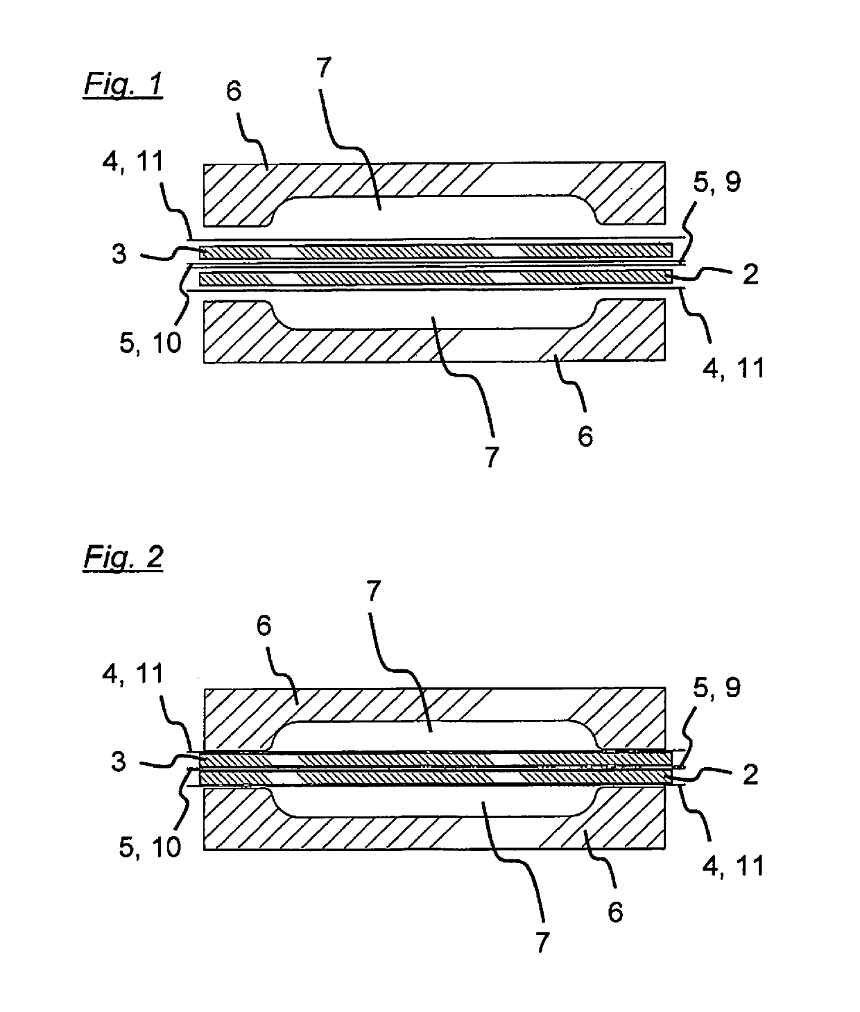
[0020]The recess plate manufactured according to the invention and the associated method are subsequently described in more detail with reference to the drawing figures, showing schematic cuts through the sheets, molds, and the resulting recess plate during four steps in the manufacturing process.

[0021]In manufacturing a recess plate 1 according to the invention, as shown in FIG. 1, a stack of two sheets 2, 3 from glass-fiber reinforced fabric, soaked with liquid PE, each lined by two protective sheets 4, 5—here: plastic foils—is inserted between two female solid molds 6.

[0022]The solid molds 6 are then pressed, and clamped (clamps not shown) together, to ensure sealing of the recesses 7 inside, as shown in FIG. 2.

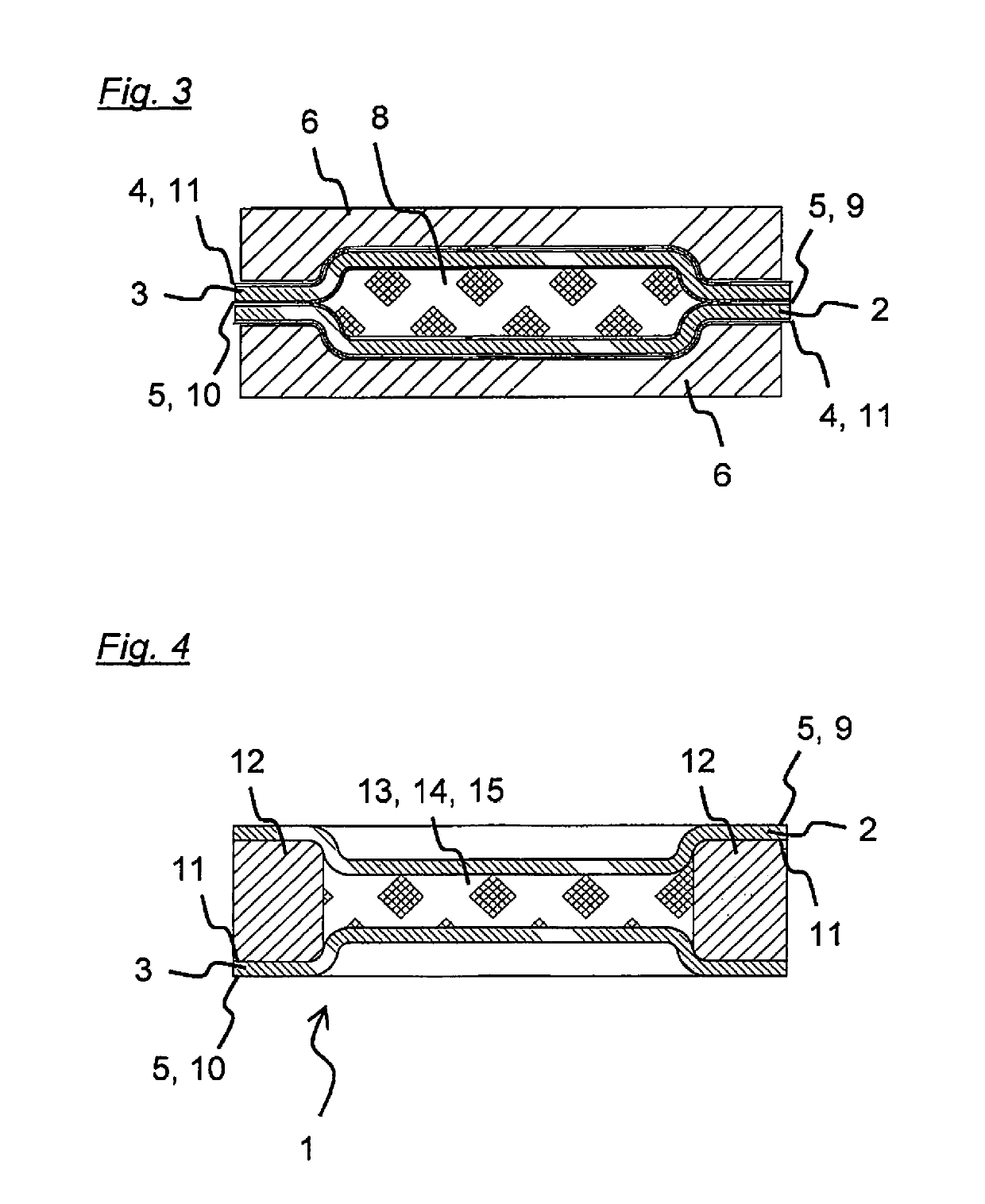
[0023]As shown in FIG. 3, hot water 8 is then fed between the two sheets 2, 3, pressing the same into the recesses 7. After hardening of the PE, the hot water 8 is discharged, the solid molds 6 are opened. Until now, the first surface 9 of the first sheet 2 and the second ...


PUM

PropertyMeasurementUnit
liquid fractionaaaaaaaaaa
differential pressureaaaaaaaaaa
differential pressuresaaaaaaaaaa

Abstract

A recess plate designed for use in a filter device for filtering a suspension includes a stationary head piece and a movable end piece, and a pack including copies of the recess plate, having a filter chamber inside the pack, adjoining the recess plate, having a first pipe for filling the suspension into the filter chamber, having a filter cloth for collecting a solid content out of the suspension, and having a second pipe for discharging a liquid fraction of the suspension out of the filter chamber as a filtrate, wherein the filter device may be closed before filtering by forcing the end piece in direction of the head piece, and opened after filtering by releasing the end piece, and moving the end piece away from the head piece for removing the filter cake from the filter cloth.

Description

CROSS-REFERENCE TO RELATED APPLICATION[0001]This application is a Continuation of PCT Patent Application Serial No. PCT / EP2014 / 003455 filed Dec. 22, 2014 the disclosure of this application is expressly incorporated herein by reference in its entirety.TECHNICAL FIELD[0002]The invention relates to a method for manufacturing a recess plate to be used in a filter device for filtering a suspension, the filter device having a stationary head piece and a movable end piece, and a pack including copies of the recess plate, having a filter chamber inside the pack, adjoining the recess plate, having a first pipe for filling the suspension into the filter chamber, having a filter cloth for collecting a solid content out of the suspension, and having a second pipe for discharging a liquid fraction of the suspension out of the filter chamber as a filtrate, wherein the filter device may be closed before filtering by forcing the end piece in direction of the head piece, and opened after filtering b...

Claims


Application Information

Patent Timeline
Patent Type & Authority Patents(United States)
IPC IPC(8): B01D25/00B01D25/21B01D25/28B01D25/30B01D25/12B29C44/42B29C70/42B29C44/12B29K105/04B29K309/08B29L7/00B29L31/14
CPCB01D25/001B01D25/215B01D25/285B01D25/302B01D25/12B29C44/42B29C70/42B29K2023/06B29L2031/14B29L2007/002B29K2309/08B29K2105/04
Inventor BÖHNKE, BERND
Owner OUTOTEC FINDLAND OY
Why Eureka
Try Eureka