Crane tower

a crane and tower technology, applied in the direction of towers, buildings, constructions, etc., can solve the problems of heavy and expensive cranes, inability to unite two opposite endeavors with conventional cranes, and huge transport expenditure, and achieve high load, load bearing, and resistance. high

Active Publication Date: 2019-08-27
LIEBHERR WERK BIBERACH
View PDF83 Cites 3 Cited by
  • Summary
  • Abstract
  • Description
  • Claims
  • Application Information

AI Technical Summary

Benefits of technology

[0022]In this context, it is imaginable to configure the tension element as a jacketed, high-strength fiber rope, the fiber rope comprising preferably aramid fibers. These high-strength, jacketed fiber ropes are able to bear particularly high loads and are particularly resistant and their load bearing capacity can easily be adapted to the characteristics demanded. Moreover, they have a very low weight and, due to their flexibility, they are ideal for forming tension members of increased length. In addition, they can be transported preferably in a condition in which they are wound onto a drum and they can be installed with little mounting effort. This results in savings as regards crane transport and mounting.

Problems solved by technology

Aspects that are opposed to this endeavor are the highest possible hook height and the highest possible bending resistance of the crane, which necessitate suitable dimensions of the components of the tower, whereby the crane tower is rendered heavy and expensive.
These two opposite endeavors cannot be united by conventional cranes.
Nevertheless, the transport expenditure is enormous.

Method used


Image

  • Crane tower
  • Crane tower
  • Crane tower

Examples


Embodiment Construction

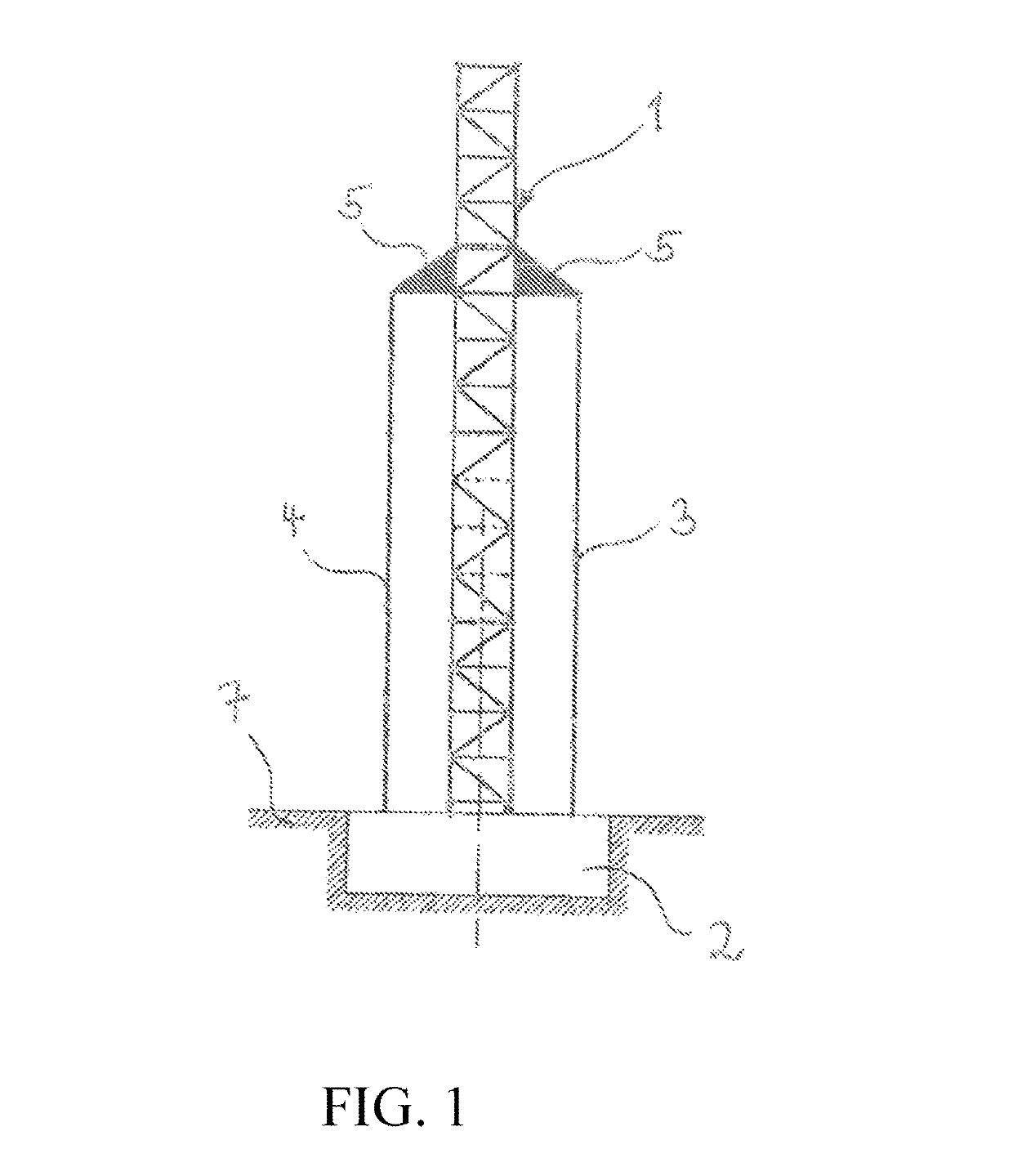
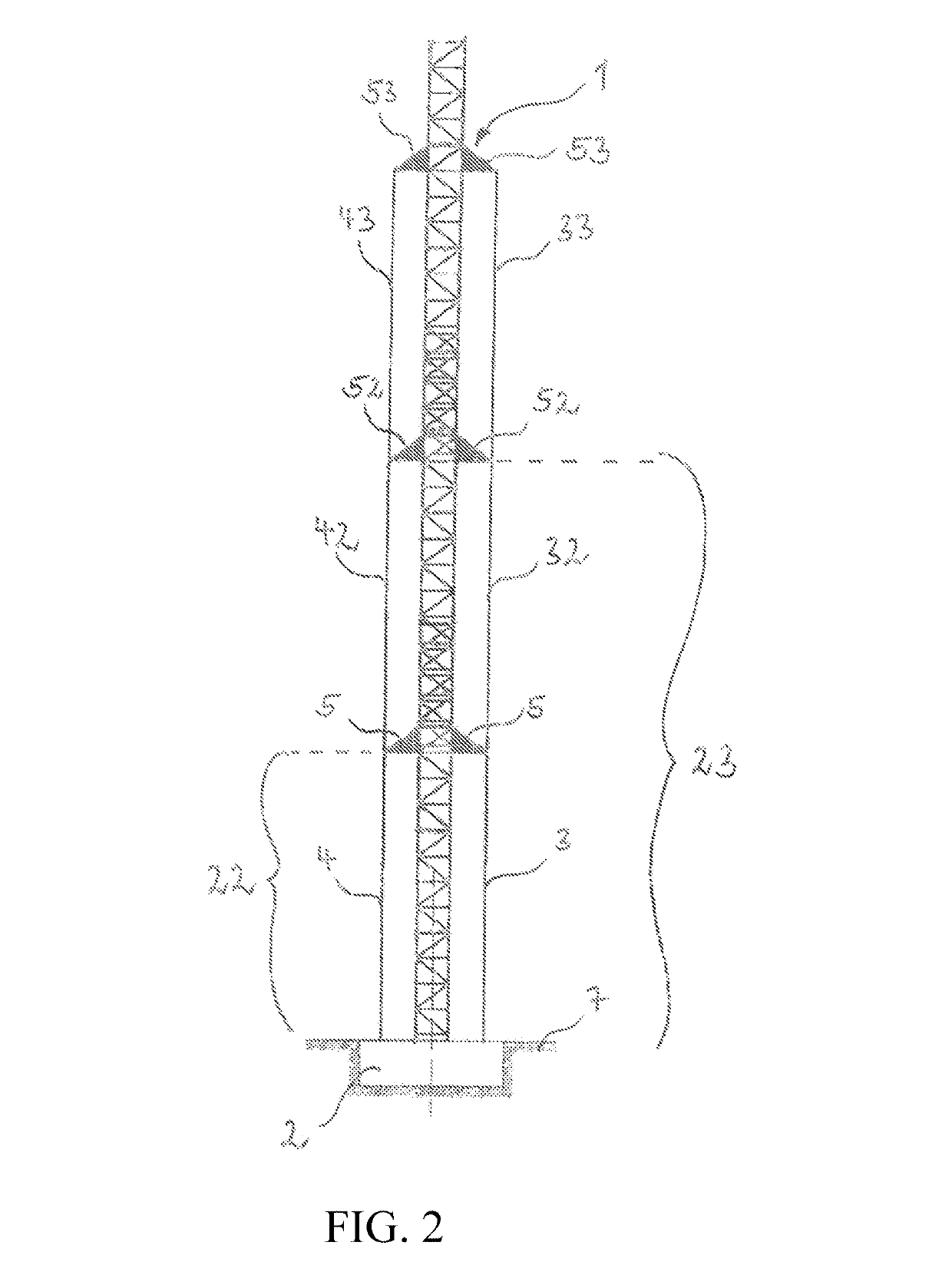
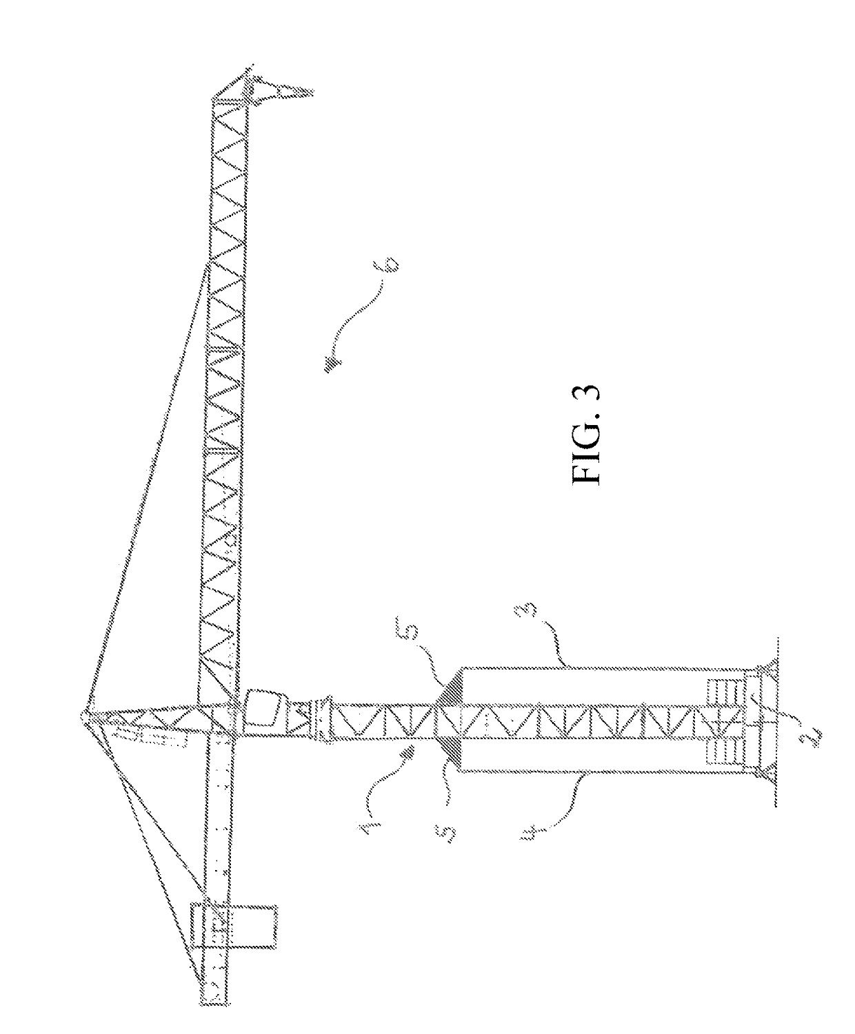
[0030]FIG. 1 shows a crane tower 1 that is fixed to a crane tower base 2. The crane tower base 2 has an upper surface, which faces the crane tower 1 and whose level is similar to that of the ground 7 surrounding the crane tower base 2. On a level spaced apart from the crane tower base 2, the crane tower 1 has provided thereon coupling elements 5 projecting from the crane tower 1. Each coupling element 5 has a tension element 3; 4, which is associated therewith and which connects the coupling element 5 to the crane tower base 2. The tension element 3; 4 extends downwards from its point of connection with the coupling element 5, substantially parallel to the longitudinal direction of the crane tower 1. Alternatively, the tension element 3; 4 may, however, also extend, in a manner that is here not shown, at an oblique angle or “criss-cross” relative to the crane tower base 2 from its point of connection with the coupling element 5. Due to the bracing of the tension element, the crane t...


PUM


Abstract

The present invention relates to a crane tower comprising a crane tower base, which has a crane tower or a crane tower element fixed thereto and from which the crane tower extends upwards, and a tension element for bracing the crane tower 1 on the crane tower base. The tension element has one of its two ends connected to the crane tower base and its respective other end connected to the crane tower or to a coupling element that is connected to the crane tower. The crane tower is characterized in that the tension element extends outside of the crane tower. It is thus possible to reduce the dimensions of the crane tower without causing any change of bending resistance or to increase the bending resistance on the basis of the same dimensions.

Description

CROSS-REFERENCE TO RELATED APPLICATION[0001]The present application is a U.S. National Phase of International Patent Application Serial No. PCT / EP2016 / 000513, entitled “CRANE TOWER,” filed on Mar. 23, 2016. International Patent Application Serial No. PCT / EP2016 / 000513 claims priority to German Patent Application No. 10 2015 003 982.2, filed on Mar. 26, 2015. The entire contents of each of the abovementioned applications are hereby incorporated by reference in their entirety for all purposes.TECHNICAL FIELD[0002]The present invention relates to a crane tower as well as to a rotating tower crane comprising this crane tower.BACKGROUND AND SUMMARY[0003]An important element of cranes is the crane tower, which accounts to a substantial degree for the achievable crane hook height. In top-slewing tower cranes, the crane tower has the function of dissipating the occurring loads from the upper part of the crane as well as forces acting on the upper part to the base point of the crane tower.[0...

Claims


Application Information

Patent Timeline
Patent Type & Authority Patents(United States)
IPC IPC(8): E04H12/20B66C23/28B66C23/02B66C23/74
CPCB66C23/283E04H12/20B66C23/02B66C23/74
Inventor MAYER, JOACHIM
Owner LIEBHERR WERK BIBERACH
Why Eureka
Try Eureka