Protection device

a protection device and battery technology, applied in the direction of emergency protection devices, electrical equipment, and condition indication of switching devices, can solve the problems of battery burnout or explosion of cellular phones or portable products during charging or discharging, and achieve the effects of increasing voltage endurance, increasing resistance, and increasing voltage enduran

Active Publication Date: 2019-08-27
POLYTRONICS TECH
View PDF7 Cites 4 Cited by
  • Summary
  • Abstract
  • Description
  • Claims
  • Application Information

AI Technical Summary

Benefits of technology

[0007]The present application provides a protection device for over-current, over-voltage and / or over-temperature protection. The protection device comprises at least two heating elements of different resistances. To adapt to an applying voltage, either one of the heating elements can be automatically activated to heat the fusible element, thereby increasing the voltage endurance and enlarging voltage application range.
[0020]In the protection device of the present application, the resistance of the second heating element is at least twice that of the first heating element. For a low voltage, most of current flows through the first heating element of a low resistance and the first heating element heats up to heat the fusible element. When the voltage exceeds a predetermined voltage, the first heating element cannot withstand it and therefore is blown to cut off the current flowing therethrough. The current is switched to the second heating element in parallel connection with the first heating element, and then the second heating element heats up to blow the fusible element. The second heating element of a larger resistance can withstand a higher voltage in comparison with the first heating element. According to different applying voltages, the protection device can automatically select the first or second heating element to heat and blow the fusible element. It is advantageous to increase voltage endurance and enlarge voltage application range of the protection device.

Problems solved by technology

However, burnout or explosion of batteries of cellular phones or portable products during charging or discharging is often seen.

Method used


Image

  • Protection device
  • Protection device
  • Protection device

Examples


Embodiment Construction

[0034]The making and using of the presently preferred illustrative embodiments are discussed in detail below. It should be appreciated, however, that the present application provides many applicable inventive concepts that can be embodied in a wide variety of specific contexts. The specific illustrative embodiments discussed are merely illustrative of specific ways to make and use the invention, and do not limit the scope of the invention.

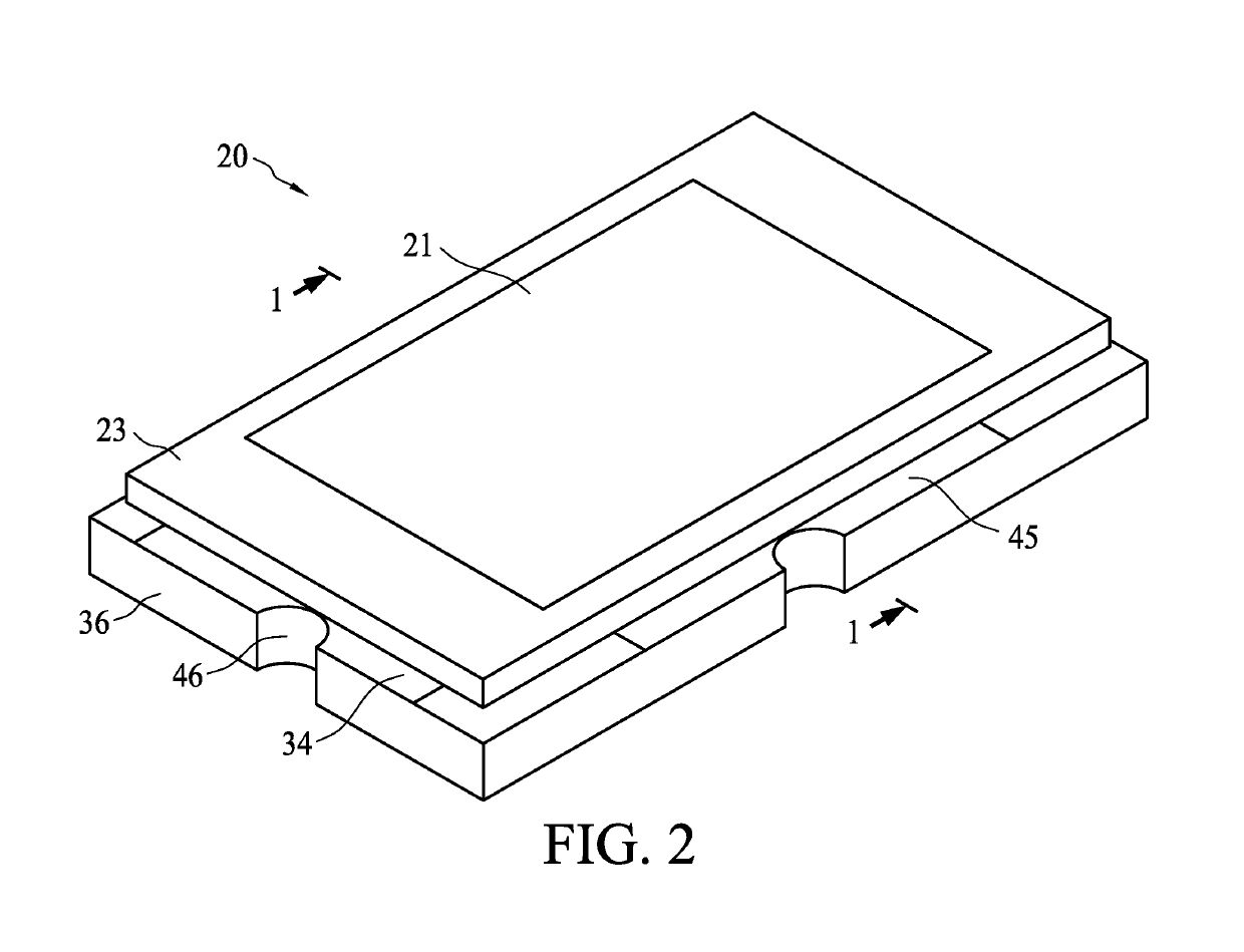
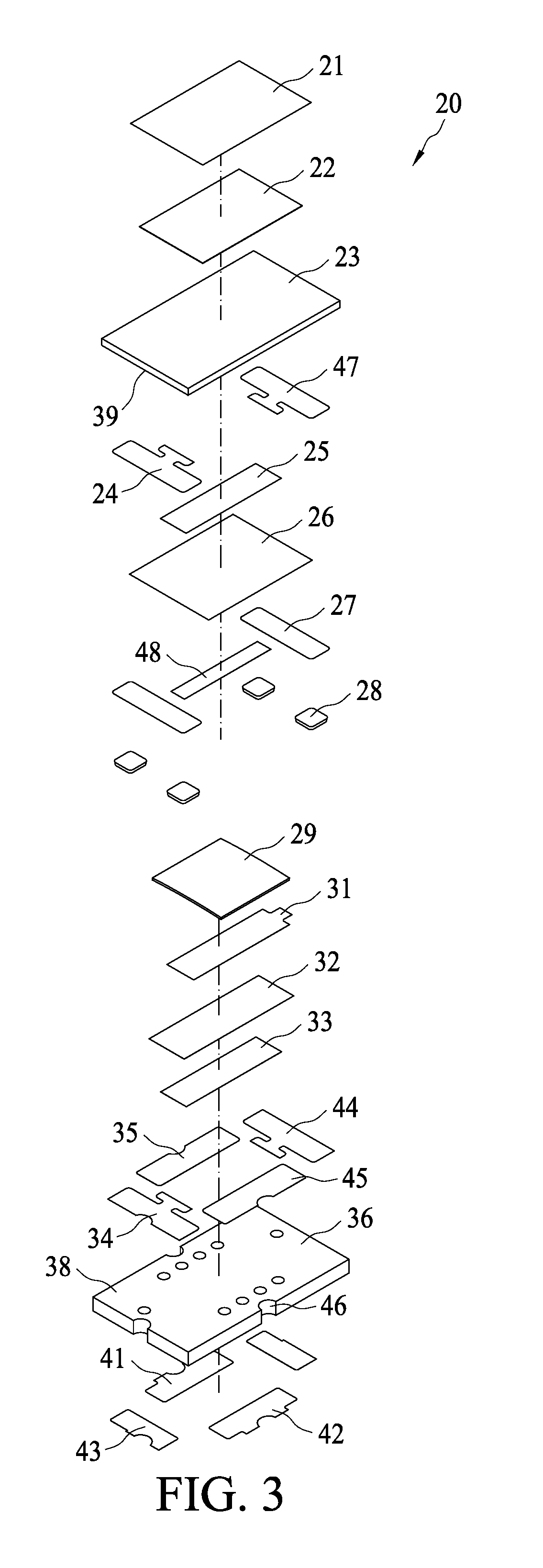
[0035]FIG. 2 shows a protection device 20 in accordance with an embodiment of the present application. FIG. 3 shows an exploded view of the protection device 20. FIG. 4 shows a cross-sectional view of the protection device 20 along line 1-1 in FIG. 2. The protection device 20 essentially comprises a first planar substrate 36, a second planar substrate 23, a first heating element 33, a second heating element 25 and a fusible element 29. An upper surface of the first planar surface 36 is a first surface 38 on which a first electrode 35, a second elec...


PUM


Abstract

A protection device comprises a first planar substrate, a second planar substrate, a heater and a fusible element. The first planar substrate comprises a first surface, and the second planar substrate comprises a second surface facing the first surface. The heater comprises a first heating element and a second heating element in parallel connection, and the first heating element is disposed on the first surface. The fusible element is disposed on the first surface and adjacent to the first and second heating elements, thereby the fusible element is melted by absorbing the heat generated by the first heating element and / or second heating element. The second heating element has a resistance at least twice that of the first heating element.

Description

BACKGROUND OF THE INVENTION(1) Field of the Invention[0001]The present application relates to a protection device. More specifically, it relates to a protection device capable of preventing over-voltage, over-current and / or over-temperature.(2) Description of the Related Art[0002]Fuses containing low-melting metals, e.g., lead, tin or antimony, are well-known protection devices to cut off currents. To prevent over-current and over-voltage, various protection devices are continuously developed. For example, a device containing a substrate on which a heating layer and a low-melting metal layer are stacked in sequence. The heating layer heats up in the event of over-voltage, and then the heat is transferred upwards to the low-melting metal layer. As a result, the low-melting metal layer is melted and blown to sever currents flowing therethrough, so as to protect circuits or electronic apparatuses.[0003]Recently, mobile apparatuses such as cellular phones and laptop computers are widely...

Claims


Application Information

Patent Timeline
Patent Type & Authority Patents(United States)
IPC IPC(8): H01H85/00H01H85/04H01H85/20H01H69/02H01H85/041
CPCH01H71/04H01H69/02H01H85/0047H01H85/0052H01H85/04H01H85/20H01H2085/0414
Inventor SU, TSUNG MINCHEN, CHIA MAOWANG, DAVID SHAU CHEW
Owner POLYTRONICS TECH
Why Eureka
Try Eureka