Micro mirror array, manufacturing method of the micro mirror array, and floating display device including the micro mirror array

a micro mirror array and manufacturing method technology, applied in the field of micro mirror arrays, can solve the problems of unrealistic virtual image and limited application of half mirror display devices, and achieve the effect of high cubic or 3d effect and realistic half mirror display devices

Active Publication Date: 2019-09-03
LG ELECTRONICS INC
View PDF19 Cites 0 Cited by
  • Summary
  • Abstract
  • Description
  • Claims
  • Application Information

AI Technical Summary

Benefits of technology

[0014]Therefore, the present invention has been made in view of the above problems, and it is an object of the present invention to provide a floating display device that is capable of displaying an image that is highly realistic and exhibits a high cubic or 3D effect, a micro mirror array used in the floating display device, and a manufacturing method of the micro mirror array.
[0015]It is another object of the present invention to provide a floating display device that is capable of interacting with a user, a micro mirror array used in the floating display device, and a manufacturing method of the micro mirror array.
[0016]In accordance with an aspect of the present invention, the above and other objects can be accomplished by the provision of a manufacturing method of a micro mirror array including forming a mirror surface on a polymer film, bonding a plurality of polymer films, each having the mirror surface formed thereon, cutting the bonded polymer films to manufacture a primary micro mirror array, forming an additional mirror surface on the manufactured primary micro mirror array, bonding a plurality of primary micro mirror arrays, each having the additional mirror surface formed thereon, and cutting the bonded primary micro mirror arrays.

Problems solved by technology

However, the image formed by the half mirror type display device is a rear floating image, which cannot interact with the user and exhibits a low cubic or 3D effect.
For these reasons, the half mirror type display device is only applicable in limited places, such as performance stages.
As a result, the virtual image is not realistic.

Method used


Image

  • Micro mirror array, manufacturing method of the micro mirror array, and floating display device including the micro mirror array
  • Micro mirror array, manufacturing method of the micro mirror array, and floating display device including the micro mirror array
  • Micro mirror array, manufacturing method of the micro mirror array, and floating display device including the micro mirror array

Examples


Embodiment Construction

[0033]Advantages, features and methods for achieving those of embodiments may become apparent upon referring to embodiments described later in detail together with attached drawings. However, embodiments are not limited to the embodiments disclosed hereinafter, but may be embodied in different modes.

[0034]In the drawings, parts that are irrelevant to embodiments are omitted for convenience of description and clarity. The embodiments are provided for perfection of disclosure and informing a scope to persons skilled in this field of art. The same reference numbers may refer to the same elements throughout the specification.

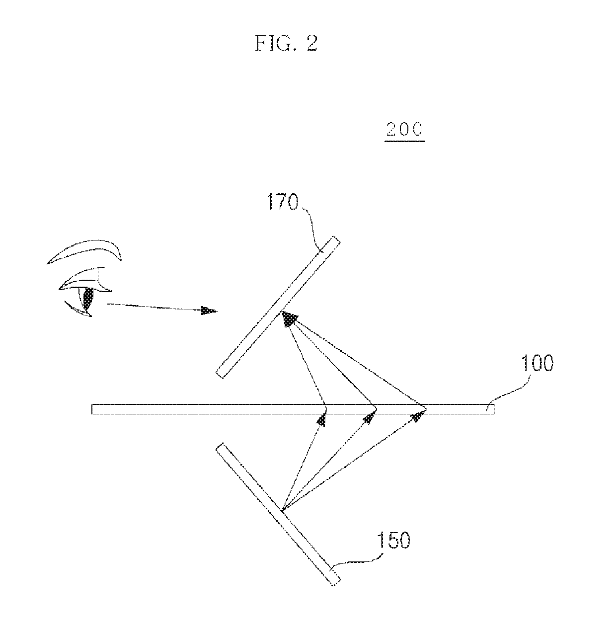
[0035]FIG. 2 is a conceptual view showing a floating display device according to an embodiment of the present invention.

[0036]Referring to FIG. 2, a floating display device 200 according to an embodiment of the present invention may include a display unit 150 for displaying an image and a micro mirror array 100 for reflecting the image displayed on the display unit ...


PUM

PropertyMeasurementUnit
angleaaaaaaaaaa
latticeaaaaaaaaaa
distanceaaaaaaaaaa

Abstract

Discussed is a manufacturing method of a micro mirror array including forming a mirror surface on a polymer film, bonding a plurality of polymer films, each having the mirror surface formed thereon, cutting the bonded polymer films to manufacture a primary micro mirror array, forming an additional mirror surface on the manufactured primary micro mirror array, bonding a plurality of primary micro mirror arrays, each having the additional mirror surface formed thereon, and cutting the bonded primary micro mirror arrays. The micro mirror array is used to form a high-quality floating image.

Description

CROSS-REFERENCE TO RELATED APPLICATION[0001]This application claims the priority benefit of Korean Patent Application No. 10-2015-0101808, filed on Jul. 17, 2015 and Korean Patent Application No. 10-2015-0165220 filed on Nov. 25, 2015 in the Korean Intellectual Property Office, which are all incorporated herein by reference.BACKGROUND OF THE INVENTION[0002]1. Field of the Invention[0003]Embodiments of the present invention relate to a micro mirror array, a manufacturing method of the micro mirror array, and a floating display device including the micro mirror array.[0004]2. Description of the Related Art[0005]As a result of the growth of the information society, the demand for various display devices has increased along with the increase in the amount of multimedia content.[0006]In addition, research has been increasingly conducted into a digital signage, in which display devices are used outdoors for marketing, advertisements, broadcasting, the provision of information, etc.[0007]M...

Claims


Application Information

Patent Timeline
Patent Type & Authority Patents(United States)
IPC IPC(8): G02B5/136G02B27/22G02B17/00B29D11/00G02B5/124G02B30/60
CPCB29D11/00596G02B27/2292G02B5/124G02B17/006G02B17/002B29D11/00932B29D11/00865G02B5/136G02B30/60G02B30/56
Inventor KIM, WOOTAEKIM, JINBEOM
Owner LG ELECTRONICS INC
Why Eureka
Try Eureka