See-through type display apparatus

a display apparatus and see-through technology, applied in the field of see-through display apparatus, can solve the problems of large mismatch degree, increased apparent unnaturalness of display, and inability to apply display technology to actual products, etc., to achieve high real-time effect, increase visual convenience of user, and small siz

Active Publication Date: 2019-10-24
SAMSUNG ELECTRONICS CO LTD
View PDF16 Cites 10 Cited by
  • Summary
  • Abstract
  • Description
  • Claims
  • Application Information

AI Technical Summary

Benefits of technology

[0009]One or more example embodiments may provide a see-through type display apparatus capable of simultaneously providing a multi-focal characteristic and a wide viewing angle while having a small size, thereby increasing a visual convenience of a user and implementing a highly real augmented reality (AR).

Problems solved by technology

Therefore, this increases the apparent unnaturalness of the display.
The biggest contributor to this apparent unnaturalness is the mismatch between vergence (the binocular angle formed by binocular parallax) and the accommodation in the lens of a viewer's eye.
This is a very well known problem in existing 3D displays and the depth range of 3D images is limited to alleviate it.
However, due to the characteristics of AR, since it is impossible to specify whether the real object and the virtual image interact with each other in real time, and it is impossible to know at what distance the real object is located, it is difficult to determine a degree of mismatch caused by a real-time interaction and thus it is very likely that the mismatch degree is large.
However, these display technologies have not been applied to actual products due to the high-speed driving of displays and multi-focal optics, the limitations of the viewing angle, the increase in computational amount, and the size.

Method used


Image

  • See-through type display apparatus
  • See-through type display apparatus
  • See-through type display apparatus

Examples


Embodiment Construction

[0045]Hereinafter, see-through type display apparatuses according to example embodiments will be described with reference to the accompanying drawings. In the drawings, like reference numerals refer to like elements, and the sizes of elements may be exaggerated for clarity of illustration. Embodiments described herein are for illustrative purposes only, and various modifications may be made therefrom.

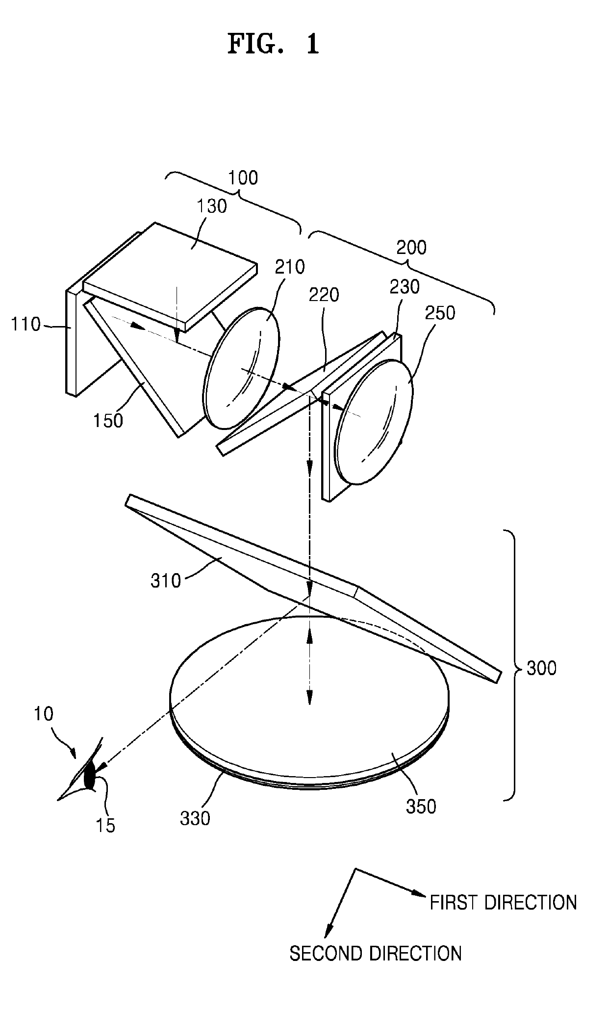
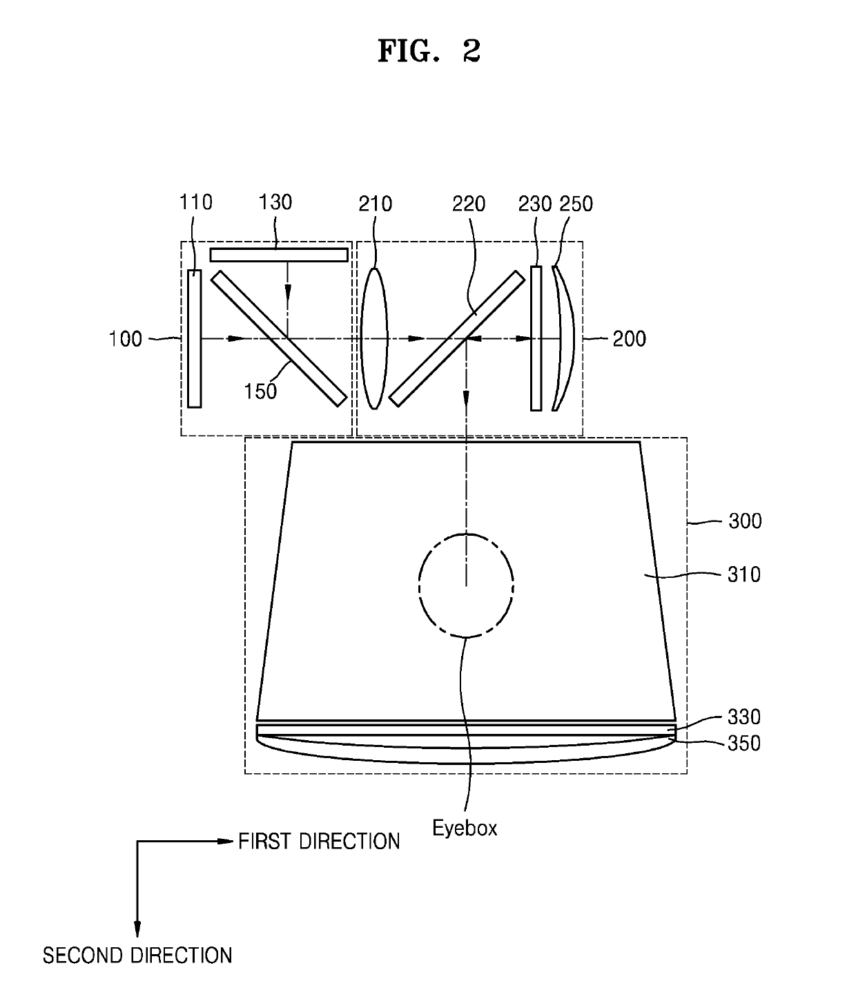
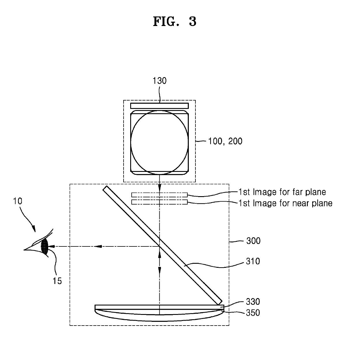
[0046]FIG. 1 is a perspective view schematically showing a see-through type display apparatus according to an example embodiment. FIGS. 2 and 3 schematically show a configuration of FIG. 1.

[0047]Referring to FIGS. 1 to 3, the see-through type display apparatus (also called a transparent type display apparatus) may include an image forming unit 100, a relay optical system 200 transmitting an image output from the image forming unit 100 and forming a primary imaging image, and an optical combiner 300 reimaging the primary imaging image transmitted by the relay optical system 200 and produ...


PUM


Abstract

A see-through type display apparatus includes an image forming unit; a relay optical system configured to transmit an image provided from the image forming unit and to form a primary imaging image; and an optical combiner configured to reimage the primary imaging image transmitted from the relay optical system and to form a multi-depth plane. The relay optical system includes a lens; a polarizer arranged at an angle with respect to an optical axis and configured to reflect light of light of a first polarization and transmit light of second polarization therethrough; a condensing mirror member configured to reflect and condense light incident from the polarizer; and a polarization converter configured to convert a polarization of light transmitted between the polarizer and the condensing mirror member.

Description

CROSS-REFERENCE TO RELATED APPLICATION[0001]This application claims priority from Korean Patent Application No. 10-2018-0047316, filed on Apr. 24, 2018, in the Korean Intellectual Property Office, the disclosure of which is incorporated herein in its entirety by reference.BACKGROUND1. Field[0002]Apparatuses consistent with example embodiments relate to a see-through type display apparatus and more particularly to a see-through type display apparatus having a relay optical system.2. Description of the Related Art[0003]Recently, the development of electronic apparatuses and display apparatuses capable of implementing virtual reality (VR) has led to increased interest in applications using such apparatuses. As a next step for VR, a technology for implementing augmented reality (AR) and mixed reality (MR) has been researched.[0004]Unlike VR that is based on a complete virtual world, AR is a display technique that shows the real world overlapped (combined) with virtual objects or informa...

Claims


Application Information

Patent Timeline
Patent Type & Authority Applications(United States)
IPC IPC(8): G02B27/01G02B27/28G02B5/30
CPCG02B27/0176G02F1/1313G02B27/283G02B27/0172G02B5/30G02B5/3058G02B13/14G02B17/0615G02B27/286G02B2027/0185G02B17/008G02B17/08G02B27/28G02B2027/0178
Inventor LEE, CHANGKUNSEO, WONTAEKSUNG, GEEYOUNGLEE, HONGSEOK
Owner SAMSUNG ELECTRONICS CO LTD
Why Eureka
Try Eureka