Sheet guiding device and image forming apparatus

a technology of image forming apparatus and guiding device, which is applied in the direction of electrographic process apparatus, thin material processing, instruments, etc., can solve the problems of sudden change of current flowing through the sheet, inability to perform electrical control, and extremely low electrical resistance of sheets

Active Publication Date: 2019-09-03
FUJIFILM BUSINESS INNOVATION CORP
View PDF7 Cites 2 Cited by
  • Summary
  • Abstract
  • Description
  • Claims
  • Application Information

AI Technical Summary

Benefits of technology

[0007]Aspects of non-limiting embodiments of the present disclosure relate to a sheet guiding device and an image forming apparatus that suppress a sudden change of current which flows through a sheet.

Problems solved by technology

When a member having a high resistance is used as a guiding member that guides transported paper sheets, a paper sheet may electrostatically adheres to the member to cause a transport error.
These sheets have an extremely low electrical resistance as compared with a paper sheet in related art, and when the sheets are used, at the moment when a sheet transported is separated from a grounded guiding member including a conductive material, at a position slightly away from a transfer position, a current which flows through the sheet suddenly changes, and electrical control is not performed in time and a transfer error may occur.
Such a transfer error occurs not only when a black paper or an aluminum sheet is used, but also may occur under conditions in which a current which flows through a sheet increases, depending on the property of the sheet itself or the usage environment.
However, aspects of the non-limiting embodiments are not required to overcome the disadvantages described above, and aspects of the non-limiting embodiments of the present disclosure may not overcome any of the disadvantages described above.

Method used


Image

  • Sheet guiding device and image forming apparatus
  • Sheet guiding device and image forming apparatus
  • Sheet guiding device and image forming apparatus

Examples


Embodiment Construction

[0024]Hereinafter, exemplary embodiments of the disclosure will be described.

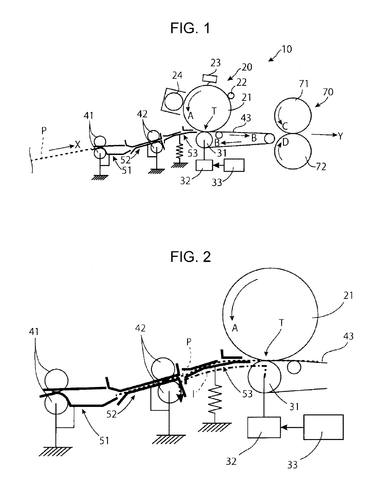
[0025]FIG. 1 is a schematic view illustrating the major components of an image forming apparatus according to an exemplary embodiment of the disclosure. The image forming apparatus illustrated in this FIG. 1 includes a sheet guiding device according to an exemplary embodiment of the disclosure.

[0026]An image forming apparatus 10 includes a toner image former 20. The toner image former 20 includes an image carrier 21 that rotates in the direction of an arrow A, and a charging unit 22, an exposure unit 23, and a developing unit 24 are further provided around the image carrier 21.

[0027]The charging unit 22 charges the image carrier 21. The exposure unit 23 radiates a charged area of the image carrier 21 with exposure light to form an electrostatic latent image on the image carrier 21. Furthermore, the developing unit 24 develops the electrostatic latent image on the image carrier 21 with toner to form a toner ...


PUM


Abstract

A sheet guiding device includes: a first guiding unit that is grounded and guides a sheet transported; and a second guiding unit that is disposed on a downstream side of the first guiding unit and grounded with a resistance higher than a resistance with which the first guiding unit is grounded, and that guides the sheet transported to the first guiding unit to a transfer position interposed between an image carrier that carries a toner image and a transfer unit that transfers the toner image on the image carrier onto the transported sheet by pinching the sheet between the image carrier and the transfer unit and applying an electric field across the image carrier and the transfer unit. The first guiding unit has a dimension decrease area in which on a surface, in contact with the sheet, of the first guiding plate on the downstream side in the sheet transport direction, a dimensional value of a portion including a first material that is a same as the first material used as a material of another surface, in contact with the sheet, of the first guiding plate on an upstream side of the downstream side in a sheet width direction crossing the sheet transport direction is decreased at a more downstream position in the sheet transport direction.

Description

CROSS-REFERENCE TO RELATED APPLICATIONS[0001]This application is based on and claims priority under 35 USC 119 from Japanese Patent Application No. 2018-116947 filed Jun. 20, 2018.BACKGROUND(i) Technical Field[0002]The present disclosure relates to a sheet guiding device and an image forming apparatus.(ii) Related Art[0003]When a member having a high resistance is used as a guiding member that guides transported paper sheets, a paper sheet may electrostatically adheres to the member to cause a transport error. Thus, the member is composed of a conductive material and grounded. However, in the case of a guiding member which is near a transfer position at which a toner image on an image carrier is electrostatically transferred onto a paper sheet, a resin with a high resistance on the order of several 100 Ω·m is used to avoid an adverse effect on the transfer.[0004]Here, Japanese Unexamined Patent Application Publication No. 2010-085491 discloses a configuration in which a transported ...

Claims


Application Information

Patent Timeline
Patent Type & Authority Patents(United States)
IPC IPC(8): G03G15/00G03G15/16B65H5/06
CPCG03G15/161G03G15/6558B65H5/062G03G15/5004G03G15/165G03G15/657G03G15/6529B65H5/36B65H2404/611B65H2404/533
Inventor TOKUYAMA, ATSUHITO
Owner FUJIFILM BUSINESS INNOVATION CORP
Why Eureka
Try Eureka