Control device for internal combustion engine

a control device and internal combustion engine technology, applied in the direction of electric control, machines/engines, mechanical equipment, etc., can solve the problem of insufficient control, and achieve the effect of reducing controllability regarding the control amoun

Inactive Publication Date: 2018-12-25
TOYOTA JIDOSHA KK
View PDF60 Cites 1 Cited by
  • Summary
  • Abstract
  • Description
  • Claims
  • Application Information

AI Technical Summary

Benefits of technology

[0011]There is room for improvement with regard to the technique disclosed in JP 2006-275172 A, too. In the first control cycle after the switching from the second control to the first control, the initial value of the I term after the switching is obtained based on the subtraction of the FF term for the FF control of the present control cycle from the I term for the FB control of the previous control cycle. However, as a result of the inventor's calculation associated with this the present application, it has been confirmed that the consideration of the I term of the previous control cycle alone during the calculation of the initial value of the I term after the switching is not sufficient to ensure the suppression of a sudden change in the command value. In addition, although the I term is represented by the sum of the previous value and the current update amount (value obtained by multiplying an I gain by a deviation), the current update amount is not reflected in the I term in a case where the initial value of the I term is set as described above. The update amount of the I term is a value that changes in accordance with the deviation and is the amount of change that is required to ensure compliance with a target value by the FB control. Accordingly, in a case where the current update amount is not reflected in the I term, the controllability regarding the control amount is reduced.
[0014]The invention provides a control device for an internal combustion engine that is capable of suppressing a sudden change in a command value given to an actuator which is attributable to control algorithm switching while entailing no reduction in controllability regarding a control amount.
[0019]According to the control device of the above-described aspect, the value obtained by adding the current value of the deviation-dependent term included in the FB control to the previous value of the command value calculated in accordance with the first control algorithm is calculated as the current value of the command value during the switching from the first control algorithm to the second control algorithm including at least the FB control, and thus a sudden change in the command value given to the actuator that is attributable to the switching of the control algorithms can be suppressed without a reduction in controllability regarding the control amount. The actuator may be a throttle placed in an intake passage of a compression ignition-type internal combustion engine. The actuator may be an actuator controlling a flow rate of exhaust gas flowing into a turbine of a turbocharger of the internal combustion engine.

Problems solved by technology

However, as a result of the inventor's calculation associated with this the present application, it has been confirmed that the consideration of the I term of the previous control cycle alone during the calculation of the initial value of the I term after the switching is not sufficient to ensure the suppression of a sudden change in the command value.

Method used


Image

  • Control device for internal combustion engine
  • Control device for internal combustion engine
  • Control device for internal combustion engine

Examples


Embodiment Construction

[0036]Hereinafter, embodiments of the invention will be described with reference to accompanying drawings. The invention is not limited to the numbers regarding the elements of the invention in the following description, such as the numbers, quantities, amounts, ranges, and the like of the elements, unless otherwise mentioned or unless the numbers are clearly specified in principle. The structures, steps, and the like in the following description are not essential for the invention unless otherwise mentioned or unless clearly specified as essential in principle.

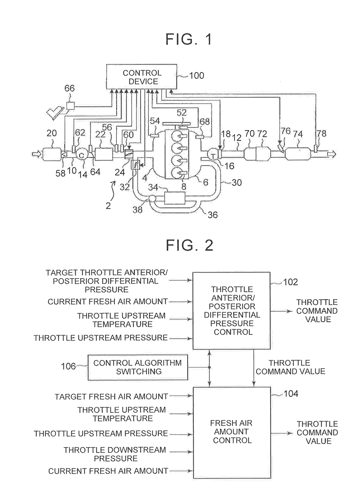
[0037]FIG. 1 is a drawing illustrating a configuration of an engine system according to an embodiment of the invention. An internal combustion engine according to this embodiment is a turbocharger-attached compression ignition-type internal combustion engine (hereinafter, simply referred to as an engine). Four cylinders are disposed in series in the engine 2, and injectors 8 are disposed for the respective cylinders. An intak...


PUM


Abstract

A control device for an internal combustion engine includes an electronic control unit configured to switch a control algorithms for a calculation of a command value of the actuator between a first control algorithm and a second control algorithm. The electronic control unit is configured to calculate a value obtained by adding a value of a term of the second control algorithm changing in accordance with the deviation calculated in a present control cycle to the command value calculated in a previous control cycle in accordance with the first control algorithm as a value of the command value calculated in the present control cycle in a first control cycle after switching from the first control algorithm to the second control algorithm. The value of the term changing in accordance with the deviation includes an update amount of an I term of the I control calculated in the present control cycle.

Description

INCORPORATION BY REFERENCE[0001]The disclosure of Japanese Patent Application No. 2015-005272 filed on Jan. 14, 2015 including the specification, drawings and abstract is incorporated herein by reference in its entirety.BACKGROUND OF THE INVENTION[0002]1. Field of the Invention[0003]The invention relates to a control device for an internal combustion engine and, more particularly, to a control device that switches control algorithms of an actuator constituting the internal combustion engine between two control algorithms.[0004]2. Description of Related Art[0005]Various actuators such as a throttle, an EGR valve, and a variable nozzle are disposed in an internal combustion engine, and an operation of the internal combustion engine is controlled based on operations of these actuators. These actuators have operation amounts that continuously vary or vary in stages. Command values that determine the operation amounts are calculated by a control device. The calculation of the command val...

Claims


Application Information

Patent Timeline
Patent Type & Authority Patents(United States)
IPC IPC(8): F02D41/14F02D41/00F02D41/26F02B37/22F02B33/40F02D41/24
CPCF02D41/1477F02B37/22F02D41/0002F02D41/0007F02D41/0077F02D41/1401F02D41/26F02B33/40Y02T10/42F02D41/2422F02D2041/0017F02D2041/0022F02D2041/141F02D2041/1409F02D2041/1418F02D2200/0406Y02T10/144F01N9/00F02B37/183F02D9/10F02D41/0052F02D41/0072F02D41/1441F01N2610/02F01N2570/14F02D2041/0067F02D2200/0414F02D2200/0404F02D2200/04Y02T10/12Y02T10/40F02D45/00
Inventor AOYAGI, SHINSUKE
Owner TOYOTA JIDOSHA KK
Why Eureka
Try Eureka