
Visual telephone system using mobile communication terminal

a mobile communication terminal and telephone system technology, applied in the field of visual telephone systems, can solve the problems of difficult to smoothly receive telephone calls and visual telephone calls, and cannot know which type of calls have been received, and achieve the effects of convenient use, excellent general versatility, and extremely easy applicability

Inactive Publication Date: 2005-06-16
KYOCERA CORP
View PDF6 Cites 10 Cited by
  • Summary
  • Abstract
  • Description
  • Claims
  • Application Information

AI Technical Summary

Benefits of technology

[0009] According to the visual telephone system using the mobile communication terminal, when a communication is received, the control unit activates an application which corresponds to data type information, appended as the header of the received data. Therefore, there is no need for controls such as activating a mode in accordance with the type. Consequently, the visual telephone system for visual communication can be controlled smoothly, and the amount of control which must be executed by the user can be greatly reduced.
[0011] According to this aspect of the visual telephone system using a mobile communication terminal, when a communication is received after the visual telephone function has been appended by attaching the detachable imaging unit to the mobile communication terminal, the control unit activates an application which corresponds to data type information, appended as the header of the in-coming information. Therefore, there is no need for controls such as activating a mode in accordance with the type of data. Consequently, the visual telephone system for visual communication can be controlled smoothly, and the amount of control which must be executed by the user can be greatly reduced.
[0013] According to the detachable imaging unit of the present invention, a visual telephone function can be appended extremely easily to a mobile communication terminal, such as a personal computer comprising a communication unit, by attaching the detachable imaging unit to the communication terminal thereof. Therefore, the detachable imaging unit has excellent general versatility, and can be used easily in various types of mobile communication terminal.

Problems solved by technology

However, when a visual telephone function has been appended to the mobile communication terminal as mentioned above, it is not possible to know which type of call has been received.
This makes it difficult to smoothly receive telephone calls and visual telephone calls.

Method used


Image

  • Visual telephone system using mobile communication terminal
  • Visual telephone system using mobile communication terminal
  • Visual telephone system using mobile communication terminal

Examples


Embodiment Construction

[0022] Preferred embodiments of the visual telephone system of the present invention will be explained with reference to the drawings.

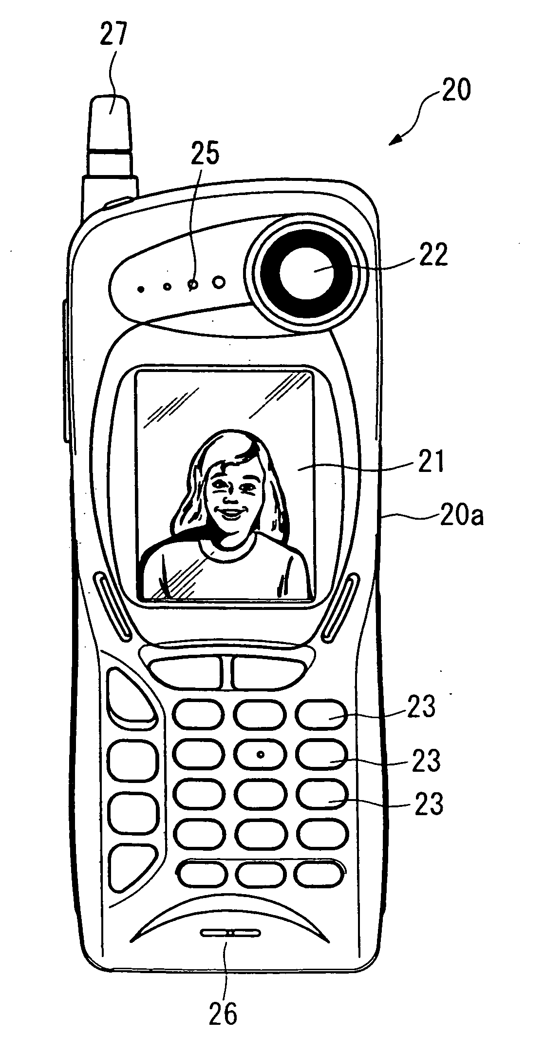
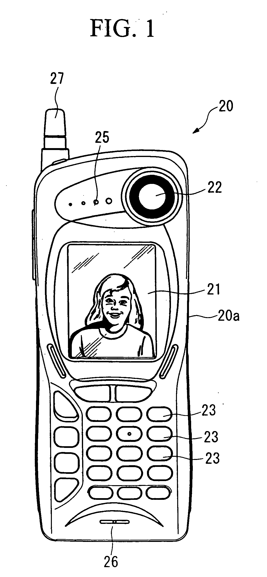
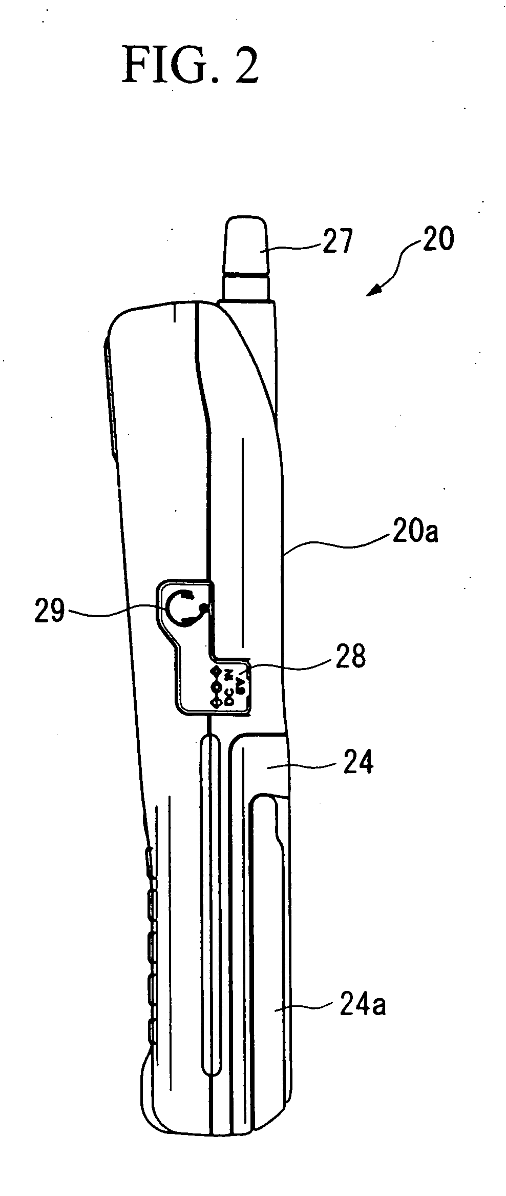
[0023]FIG. 1 is a front view showing the outside of a mobile communication terminal having a visual telephone function according to the present invention, and FIGS. 2 and 3 are side views showing the outside of the mobile communication terminal having a visual telephone function.

[0024] As shown in FIGS. 1 to 3, a monitor 21 comprises a colour liquid crystal plate, and is provided in front of a terminal main body 20a of the mobile communication terminal 20. Image information and / or communication function information in the mobile telephone apparatus, such as telephone numbers, electric field pictures and the like, are / is displayed on the monitor 21. The monitor 21 constitutes a display unit of the present embodiment.

[0025] A camera 22 comprises an image sensor (explained later) and is provided above the terminal main body 20a on the front side, and ...


PUM


Abstract

When a call-up is generated, an data type identifying unit of a CPU identifies the type of data type information which is appended as a header to received data as one of sound data, text data, and image and sound data, and displays the type on a display unit comprising a monitor. When the type is sound data or text data, an application for executing a corresponding telephone function or data communication function is activated via the user line connection. When the type is image and sound data, an application for executing a corresponding visual telephone function is activated after line connection.

Description

BACKGROUND OF THE INVENTION [0001] 1. Field of the Invention [0002] The present invention relates to a visual telephone system in which a visual telephone function is appended to a mobile communication terminal having a telephone function and a data communication function. [0003] 2. Description of the Related Art [0004] Good operability is demanded in realizing a visual telephone system comprising a visual telephone function appended to a mobile communication terminal having a telephone function and a data communication function using a communication unit which is capable of high-speed data transmission, such as PDC (Personal Digital Cellular), CDMA (Code Division Multiple Access), GSM (Global System for Mobile Communication) and PHS (Personal Handy-phone System), in addition to WCDMA (Wide band CDMA), CDMA 2000, and the like, which are being developed as next-generation technology. [0005] The reason for this is that, for example, when a telephone call has been received, the person ...

Claims


Application Information

Patent Timeline
Patent Type & Authority Applications(United States)
IPC IPC(8): H04M1/02H04M1/724H04M1/72403H04M11/00H04M11/06H04N7/14H04Q7/32
CPCH04M1/0214H04M1/0256H04M1/72519H04N2007/145H04M2250/52H04N7/142H04N7/147H04M1/72522H04M1/72403H04M1/724H04N7/14
Inventor SABURI, KAZUMIINOUE, HITOSHISHIBATA, YOSHIYUKI
Owner KYOCERA CORP
Learn More