Lane departure suppressing apparatus

a technology of lane departure and suppressor, which is applied in the direction of road vehicle traffic control, brake systems, instruments, etc., can solve the problems of insufficient control amount of departure support control, inability to accurately identify the type of lane mark, and inability to appropriately perform departure support control, etc., to reduce the width of avoidance margins, and increase the intensity of departure suppression support

Inactive Publication Date: 2018-04-19
TOYOTA JIDOSHA KK
View PDF1 Cites 10 Cited by
  • Summary
  • Abstract
  • Description
  • Claims
  • Application Information

AI Technical Summary

Benefits of technology

[0008]The above object of embodiments of the present invention can be achieved by a lane departure suppressing apparatus comprising: a supporter configured to perform departure suppression support for suppressing departure of a vehicle from a driving lane on which the vehicle is currently traveling; a detector configured to detect an adjacent area adjacent to the driving lane; a calculator configured to calculate an adjacent margin width, which is width of an area in which the vehicle can perform an avoidance action, out of the adjacent area; and a controller configured to control said supporter to increase intensity of the departure suppression support as the avoidance margin width becomes smaller.
[0009]According to the lane departure suppressing apparatus in embodiments of the present invention, if the calculated avoidance margin width is relatively small, adjustment is performed to relatively increase the intensity of the departure suppression support (in other words, to relatively increase a control amount by the departure suppression support). It is thus possible to certainly suppress the departure of the vehicle if the vehicle has a risk of collision. On the other hand, if the calculated avoidance margin width is relatively large, adjustment is performed to relatively reduce the intensity of the departure suppression support (in other words, to relatively reduce the control amount by the departure suppression support). It is thus possible to prevent excessive departure suppression support from being performed when the departure of the vehicle is not a big problem.
[0011]According to this aspect, the intensity of the departure suppression support is adjusted in accordance with the number of adjacent lanes. It is thus possible to easily determine the situation around the vehicle and perform the departure suppression support with appropriate intensity.
[0013]According to this aspect, the avoidance margin degree is calculated by dividing the calculated avoidance margin width by the predetermined width, one example of which is the width of a lane on which the vehicle can travel. If the intensity of the departure suppression support is adjusted in accordance with the avoidance margin degree, it is possible to more accurately determine the situation around the vehicle and perform the departure suppression support with appropriate intensity, in comparison with when the avoidance margin width is used as it is.
[0015]According to this aspect, the departure from the driving lane can be suppressed by using a yaw moment generated by the application of the braking force to the vehicle.

Problems solved by technology

During travel of the vehicle, however, there may be a situation in which the type of the lane mark cannot be accurately identified.
In such a case, there is a possibility that the departure support control cannot be appropriately performed for the reason that the lane mark cannot be identified.
Specifically, the control amount of the departure support control may be insufficient when the departure of the vehicle is to be avoided certainly.
As described above, if the situation around the vehicle cannot be accurately determined, it is extremely hard to appropriately perform the departure support control.
If the departure support control is not appropriately performed, discomfort may be given to an occupant of the vehicle and a risk of a collision with another vehicle or an obstacle may increase, which is technically problematic.

Method used


Image

  • Lane departure suppressing apparatus
  • Lane departure suppressing apparatus
  • Lane departure suppressing apparatus

Examples


first embodiment

[0028](1) Configuration of Vehicle 1

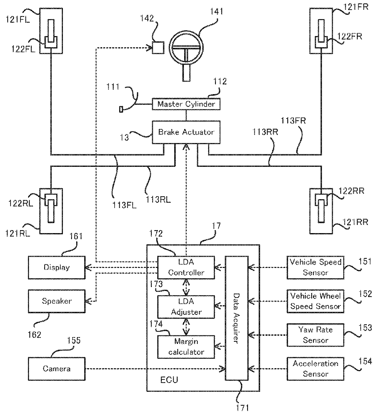
[0029]Firstly, a configuration of the vehicle 1 will be explained with reference to FIG. 1. FIG. 1 is a block diagram illustrating the configuration of the vehicle 1 according to the first embodiment.

[0030]As illustrated in FIG. 1, the vehicle 1 is provided with a brake pedal 111, a master cylinder 112, a brake pipe 113FL, a brake pipe 113RL, a brake pipe 113FR, a brake pipe 113RR, a front left wheel 121FL, a rear left wheel 121RL, a front right 121FR, a rear right 121RR, a wheel cylinder 122FL, a wheel cylinder 122RL, a wheel cylinder 122FR, a wheel cylinder 122RR, a brake actuator 13, a steering wheel 141, a vibration actuator 142, a vehicle speed sensor 151, a vehicle wheel speed sensor 152, a yaw rate sensor 153, an acceleration sensor 154, a camera 155, a display 161, a speaker 162, and an electronic control unit (ECU) 17, which is one specific example of the “lane departure suppressing apparatus”.

[0031]The brake pedal 111 is a pedal stepped ...

second embodiment

[0080]Next, a lane departure suppressing apparatus according to a second embodiment will be explained. The second embodiment is partially different from the first embodiment in the process of setting the control intensity K, and the other operation and apparatus configuration are substantially the same. Thus, hereinafter, a different part from that of the first embodiment explained above will be explained in detail, and an explanation of the same part will be omitted.

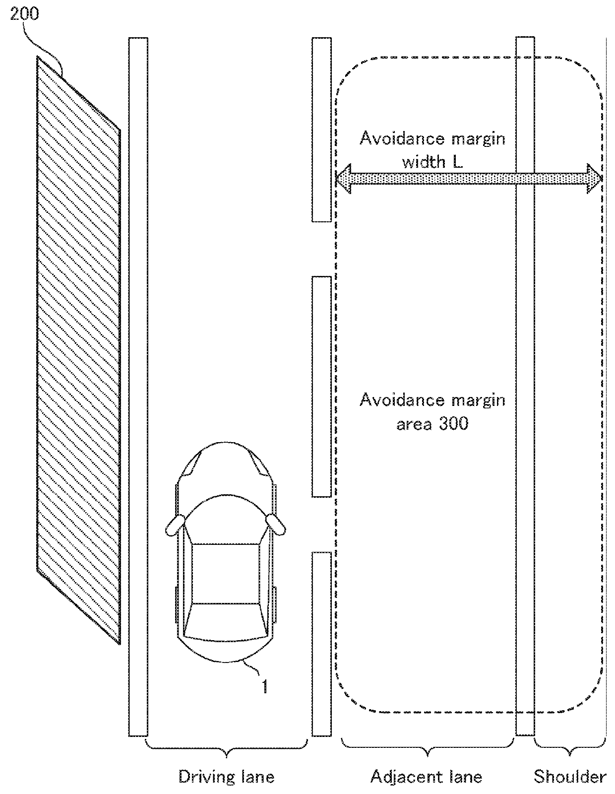
[0081]The process of setting the control intensity K according to the second embodiment will be explained with reference to FIG. 7 to FIG. 9. FIG. 7 is a flowchart illustrating a flow of the process of setting the control intensity K according to the second embodiment. FIG. 8 is a map illustrating a relation between a number N of lanes and the control intensity K. FIG. 9 is a top view illustrating one example of a vehicle that is traveling on a road and adjacent lanes. FIG. 7 carries the same step number for the same pr...

third embodiment

[0089]Next, a lane departure suppressing apparatus according to a third embodiment will be explained. The third embodiment is partially different from the first and second embodiments in the process of setting the control intensity K, and the other operation and apparatus configuration are substantially the same. Thus, hereinafter, a different part from those of the first and second embodiments explained above will be explained in detail, and an explanation of the same part will be omitted.

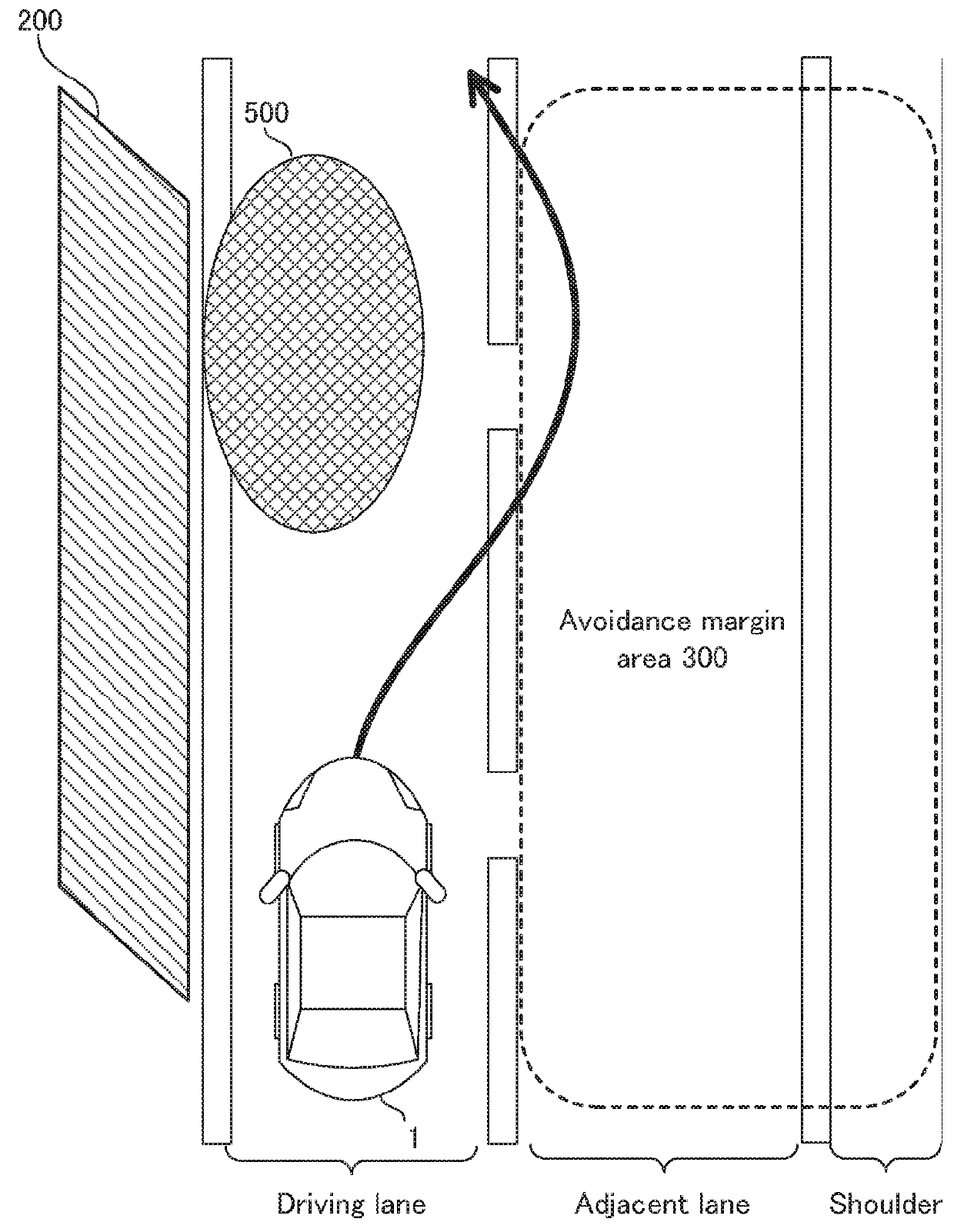
[0090]The process of setting the control intensity K according to the third embodiment will be explained with reference to FIG. 10. FIG. 10 is a flowchart illustrating a flow of the process of setting the control intensity K according to the third embodiment. FIG. 10 carries the same step number for the same process step explained by using FIG. 5.

[0091]As illustrated in FIG. 10, after the start of the process of setting the control intensity K, the margin calculator 174 recognizes the white line t...


PUM


Abstract

A lane departure suppressing apparatus is provided with: a supporter configured to perform departure suppression support for suppressing departure of a vehicle from a driving lane on which the vehicle is currently traveling; a detector configured to detect an adjacent area adjacent to the driving lane; a calculator configured to calculate an adjacent margin width, which is width of an area in which the vehicle can perform an avoidance action, out of the adjacent area; and a controller configured to control the supporter to increase intensity of the departure suppression support as the avoidance margin width becomes smaller.

Description

CROSS-REFERENCE TO RELATED APPLICATIONS[0001]This application is based upon and claims the benefit of priority of the prior Japanese Patent Application No. 2016-205300, filed on Oct. 19, 2016, the entire contents of which are incorporated herein by reference.BACKGROUND OF THE INVENTION1. Field of the Invention[0002]Embodiments of the present invention relate to a lane departure suppressing apparatus configured to suppress departure of a vehicle from a driving lane on which the vehicle is currently traveling.2. Description of the Related Art[0003]For this type of apparatus, for example, there is known an apparatus configured to suppress lane departure by automatically adjusting behavior of a vehicle if there is a possibility that the vehicle departs or deviates from a driving lane. For example, in Japanese Patent No. 5350397, there is proposed a technique / technology in which it is determined whether or not the lane departure is allowed in accordance with a type of a lane mark for def...

Claims


Application Information

Patent Timeline
Patent Type & Authority Applications(United States)
IPC IPC(8): B60T8/1755G08G1/16
CPCB60T8/17557B60T8/17551G08G1/167B60T2201/089B60T2201/083B60T2250/03B60T2201/081B60W10/184B60W30/12B60W2520/10B60W2520/105B60W2520/125B60W2520/14B60W2520/28G08G1/165
Inventor NAGAE, AKIRAINOMATA, RYOITO, HIRONORIIKEDA, MASAYUKI
Owner TOYOTA JIDOSHA KK
Why Eureka
Try Eureka