Snow removal machine

a technology of snow removal machine and moving section, which is applied in the direction of snow cleaning, way cleaning, construction, etc., can solve the problems of easy snowfall of the traveling section, so as to suppress the sudden change in the vehicle speed of the traveling section

Active Publication Date: 2020-09-17
HONDA MOTOR CO LTD
View PDF0 Cites 1 Cited by
  • Summary
  • Abstract
  • Description
  • Claims
  • Application Information

AI Technical Summary

Benefits of technology

[0020]In the above-described snow removal machine, the travel control section may control the drive source so that the traveling section gradually accelerates or decelerates to the set vehicle speed.
[0021]With such a configuration, a sudden change in vehicle speed of the traveling section can be suppressed.

Problems solved by technology

At this time, if a travel vehicle speed is comparatively large, it is easy for the traveling section to get stuck in the snow.
Such a state of the traveling section getting stuck in the snow may occur when the traveling section travels along the slope not just in the case where the oblique stepped clearing operation is performed.
However, since the reverse phase rotation control signal commensurate with the rotation speed of the electric motor is outputted to the electric motor, there is a risk of control becoming complicated.

Method used


Image

  • Snow removal machine
  • Snow removal machine
  • Snow removal machine

Examples


Embodiment Construction

[0028]A preferred embodiment of a snow removal machine according to the present invention will be presented and described below with reference to the accompanying drawings.

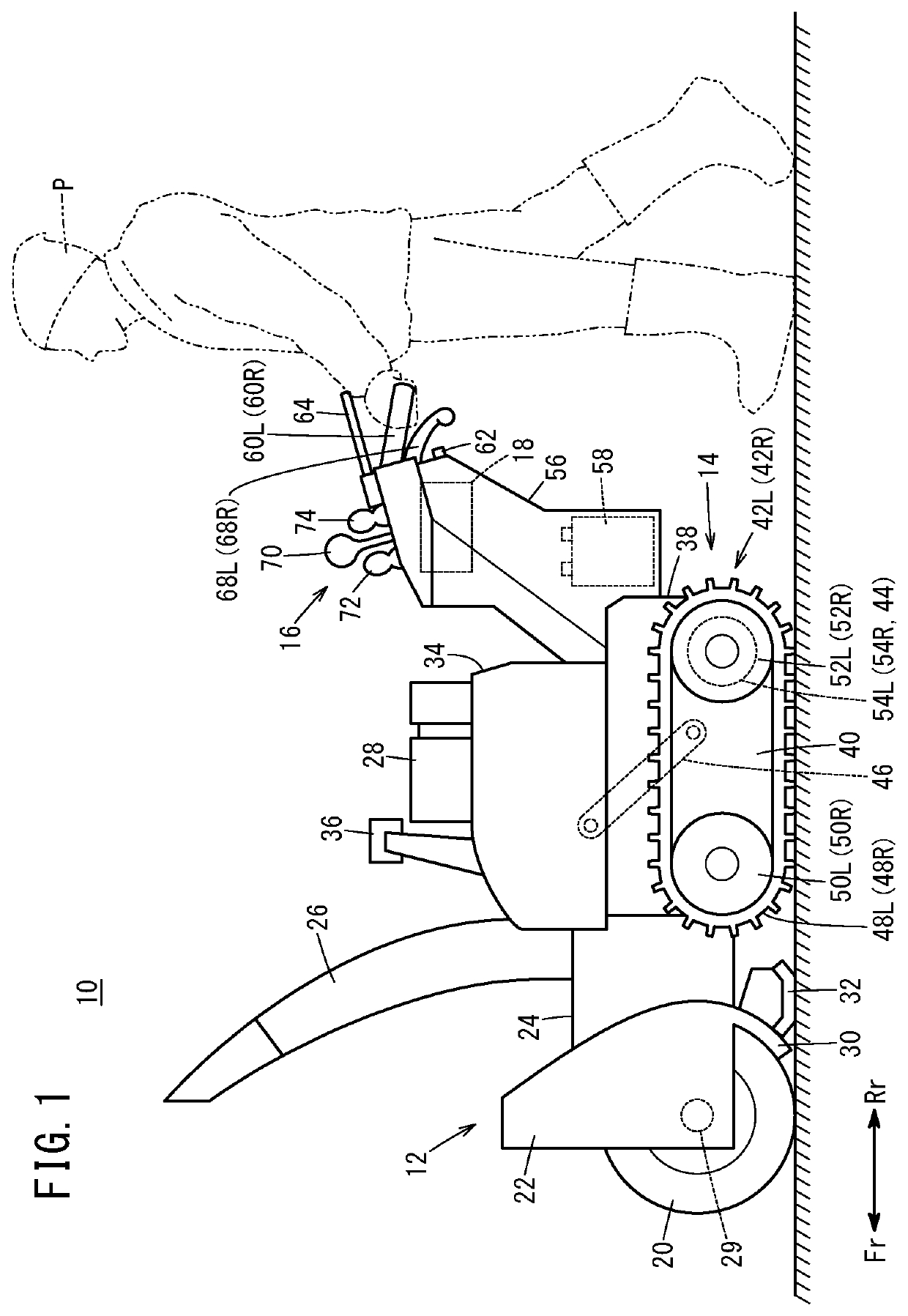
[0029]As shown in FIG. 1, a snow removal machine 10 is a walking type snow removal machine that performs snow removal work while traveling under action of a drive source 44. In FIG. 1, the arrow Fr indicates frontward of the snow removal machine 10 (the same as frontward as observed by an operator P), and the arrow Rr indicates rearward of the snow removal machine 10 (the same as rearward as observed by the operator P).

[0030]As shown in FIG. 1, the snow removal machine 10 includes a snow removal section 12, a traveling section 14, an operation section 16, and a control section 18. The snow removal section 12, which is for performing snow removal work, includes an auger 20, an auger housing 22, a blower case 24, a shooter 26, and an engine 28.

[0031]The auger 20, which is for gathering up snow, is provided in a fron...


PUM


Abstract

A snow removal machine has: a storage unit that stores a vehicle speed coefficient map indicating the relationship between an incline angle and a vehicle speed coefficient for decreasing an instructed vehicle speed; a vehicle speed coefficient setting unit that sets the vehicle speed coefficient on the basis of a detected incline angle and the vehicle speed coefficient map; and a vehicle speed setting unit that sets the vehicle speed of a traveling unit by way of multiplying the instructed vehicle speed by the set vehicle speed coefficient. The vehicle speed coefficient map sets the vehicle speed coefficient so same is smaller for larger incline angles when at least the traveling unit is going forward on an upslope. A travel control unit controls a drive source so that the traveling unit travels at the set vehicle speed set by the vehicle speed setting unit.

Description

TECHNICAL FIELD[0001]The present invention relates to a snow removal machine that includes a traveling section provided with a snow removal section for performing snow removal work and configured to travel under action of a drive source.BACKGROUND ART[0002]Japanese Laid-Open Patent Publication No. 2007-092324 discloses a snow removal machine that causes a traveling section to travel under action of an electric motor. In this snow removal machine, when the traveling section moves forward along an upslope, deceleration is achieved by outputting to the electric motor a reverse phase rotation control signal commensurate with a rotation speed of the electric motor.SUMMARY OF INVENTION[0003]Incidentally, in the snow removal machine, sometimes, when a snowfall amount is large, snow is removed in stages while traveling along a slope surface, that is, an oblique stepped clearing operation is performed. In such a case, a large load acts on a rear end portion of the traveling section, and henc...

Claims


Application Information

Patent Timeline
Patent Type & Authority Applications(United States)
IPC IPC(8): E01H5/08
CPCE01H5/08E01H5/098E01H5/04
Inventor FUKANO, JUNKAWAKAMI, TOSHIAKIMIZOROKE, TSUTOMUMOROI, ATSUSHI
Owner HONDA MOTOR CO LTD
Why Eureka
Try Eureka