Method and system for designing a common end effector for a robot which is capable of grasping plurality of parts, each having its own geometry

a robotic arm and end effector technology, applied in the field of robots, can solve the problems of inflexible variations of objects and tasks, consuming a large amount of engineering time, and the build and testing phases of a typical end effector, and achieve the effect of improving quality and grasping

Active Publication Date: 2019-09-03
BEN GURION UNIVERSITY OF THE NEGEV
View PDF2 Cites 0 Cited by
  • Summary
  • Abstract
  • Description
  • Claims
  • Application Information

AI Technical Summary

Benefits of technology

[0010]Preferably, the method further comprises a step of meshing reduction, which reduces the mesh to edges regions within each part respectively.
[0017]Preferably, a larger area defines a higher quality measure and a better grasp.

Problems solved by technology

This makes them very inflexible in terms of variations of objects and tasks.
These solutions require, however, more factory space, and thus they are very costly.
The design, build and testing phases of a typical end-effector consume considerable amounts of engineering times, and add additional costs to the final products.

Method used


Image

  • Method and system for designing a common end effector for a robot which is capable of grasping plurality of parts, each having its own geometry
  • Method and system for designing a common end effector for a robot which is capable of grasping plurality of parts, each having its own geometry
  • Method and system for designing a common end effector for a robot which is capable of grasping plurality of parts, each having its own geometry

Examples


example 1

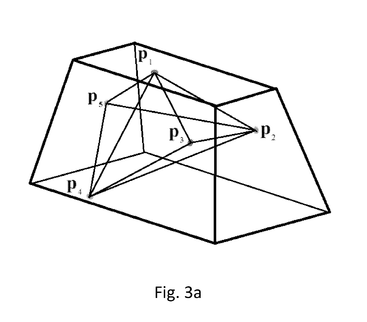
[0067]A 4-finger grasp can be described by a tetrahedron (4 facet polytope—see FIG. 4, the 4 faces are marked as Face 1-Face 4). FIG. 4 in fact represents a 4-finger grasp which is parameterized using a 14 dimensional feature vector. According to Proposition 1, six constraints are necessary to describe the tetrahedrons shape and the 8 parameters to describe the normal directions relative to the tetrahedron, resulting in a 14-dimensional feature vector. This example now considers the algorithm to calculate face 4 as the base triangle with the largest area. The parameters representing the shape of the tetrahedron, according to this algorithm, are given as follows. The length of the longest edge p1p2 of the base triangle t1=Δp1p2p3 (the largest area triangle)

d1=∥p1−p2∥  (12)

and the two angles adjacent to the edge

[0068]γ11=cos-1⁡((p3-p1)-(p2-p1)p3-p1⁢p3-p1)(13)γ12=cos-1⁡((p1-p2)-(p3-p2)p1-p2⁢p3-p2)(14)

[0069]The next two angles are the angles of the adjacent triangle t2=Δp2p3p4, which is...

example 2

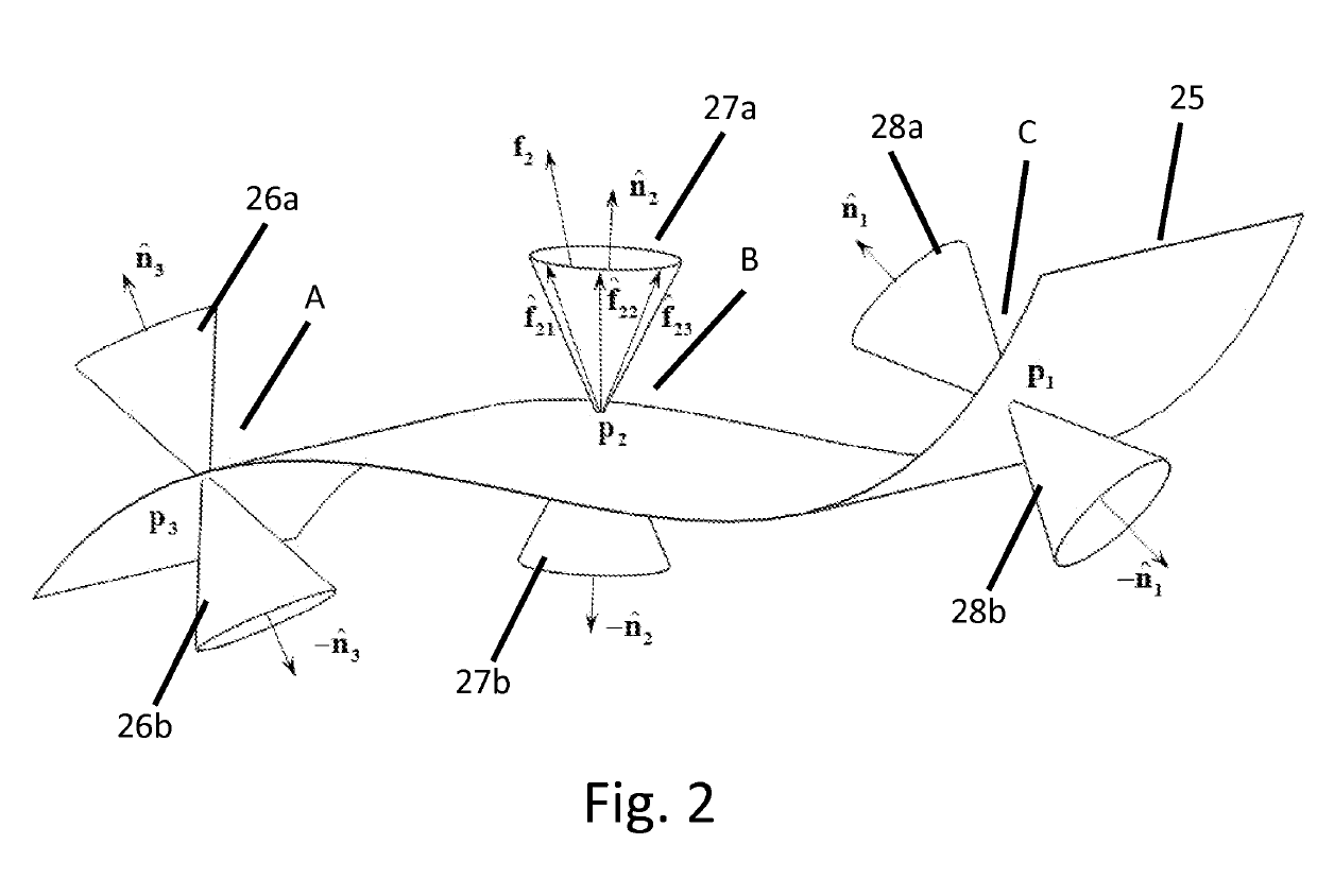
[0073]A 3-finger grasp of object B is described by a single triangle having 3 vertices. An example of such configuration of a grasp is illustrated in FIG. 5a. The position of the 3 fingers relative to each other can be injectively represented as a triangle by two angles γ1, γ2 and the edge length between them as d1, given by equations (12)-(14). However, for three contact points, the polytope degenerates into a triangle and therefore this case is not fully covered by algorithm 1. Therefore, and as shown in FIG. 5b, the normals are described at the contact points by two angles. Angle ϕi is the angle between the normal {circumflex over (n)}i and the normal to the triangle surface {circumflex over (n)}f given by

ϕi=cos−1({circumflex over (n)}−{circumflex over (n)}f),i=1,2,3  (14)

and angle ϑi is the angle of the normal's projection on the triangle surface with the adjacent triangles edge, given by the following Equation 15:

[0074]⁢π2-sgn⁡(((n^3×n^f)×a^3,1)-n^f)⁢cos-1⁡((n^3×n^f)-a^3,1),i=3...

example 3

[0116]Given that registry set contains five feature vectors u1, . . . , u5∈q that are common to two or more sets of ε1, ε2, ε3, ε4 (q=4 parts). After the performance of function JoinFCGS on ε1, . . . , ε4, each vector uj is affiliated to a binary vector ũj. For example, the five outputted binary vectors are shown in (35).

[0117]u~1=(1001)⁢⁢u~2=(0101)⁢⁢u~3=(0111)⁢⁢u~4=(1010)⁢⁢u~5=(1111)(35)

[0118]For instance, binary vector ũ1 has 1's in the first and fourth position. Therefore, the respective feature vector u1 exists in FCGS ε1 and ε4, meaning that the corresponding grasp configuration can grasp objects 1 and 4. Binary vector ũ5 equals to ({right arrow over (1)}) and therefore, it corresponds to grasp configuration which can grasp all the objects. If such a single binary vector ũ5 which satisfies condition (33) does not exist, it would be desired to search for the minimal set of binary vectors satisfying the condition. In this example, vectors ũ2 and ũ4 are taken, where their union r...


PUM


Abstract

The invention relates to a method for determining a grasp set of n gripping points for a common end effector of a robot, said end effector being used for grasping a plurality of parts, each part having its own geometry, the method comprises: (a) providing said plurality of parts in a CAD form; (b) meshing each of said parts; (c) determining for each of said parts all the possible grasps that are capable of holding the respective part by any k-contacts points end effector; (d) calculating a quality measure for each of said determined grasps; (e) calculating an allowable range for said calculated quality measures; (f) for each part, parametrizing each of its grasps that are found to be within said allowable range, by a feature vector; (g) performing a cross-part intersection between said grasps that are found to be within said allowable range, and determining those grasps that are intersected between parts; and (h) from among said intersected grasps, selecting a single grasp having a highest quality measure, said selected grasp is used for grasping said plurality of parts by said end effector.

Description

FIELD OF THE INVENTION[0001]The invention relates in general to the field of robots. More particularly, the invention relates to a method for designing a common end effector for a robotic arm, which is capable of grasping plurality of parts, each having its own shape geometry.BACKGROUND OF THE INVENTION[0002]In the industry of today, a mass production in assembly lines and manufacturing plants relies on robotics and automation lines. Robot arms that are equipped with end-effectors are key components to carry out myriad number of critical automation tasks such as material handling, paint operations, assembling, etc. A typical robot comprises one or more arms, each arm being in turn provided with an end effector. An end effector is a structure on which one or more grippers are provided at specific locations, for gripping and manipulating the respective part.[0003]Typically, each robotic end-effector of the prior art is designed, built and optimized to carry out specific actions on a s...

Claims


Application Information

Patent Timeline
Patent Type & Authority Patents(United States)
IPC IPC(8): G06G7/48G06F17/50G06F17/10G06T17/20B25J19/00
CPCB25J19/007G06T17/205G06F17/50G06F17/10G06T2210/36G06F30/00
Inventor SHAPIRO, AMIRSINTOV, AVISHAI
Owner BEN GURION UNIVERSITY OF THE NEGEV
Why Eureka
Try Eureka