Systems and methods for ultrasound pulse generation using gallium nitride field effect transistors

a gallium nitride and transistor technology, applied in the field of ultrasonic systems, can solve the problems of limited runtime of ultrasound imaging components, large equipment size of smaller ultrasound systems, and limited power, thermal management and processing capabilities of larger systems, so as to achieve high quality, reduce cost, and improve the effect of quality

Active Publication Date: 2020-11-03
ECHONOUS INC
View PDF11 Cites 0 Cited by
  • Summary
  • Abstract
  • Description
  • Claims
  • Application Information

AI Technical Summary

Benefits of technology

[0007]The present application, in part, addresses a desire for smaller ultrasound systems, having greater portability, lower cost, and ease of use for different modes of ultrasound imaging, while at the same time providing high quality measurements.

Problems solved by technology

For many years, ultrasound imaging was effectively confined to large equipment operating in a hospital environment.
Nevertheless, smaller ultrasound systems typically lack the power, thermal management, and processing capabilities of larger systems.
This generally results in limited runtime of the ultrasound imaging components, lower image resolution, and fewer features or modes of operation.
When designing an ultrasound pulser circuit to be located within the ultrasound probe, however, certain issues may exist which are not of particular importance in conventional systems that have the pulser circuits located in large equipment connected to the ultrasound probe by one or more cables.
For example, in an ultrasound pulser circuit within the ultrasound probe, power losses become significantly more important (as, for example, heat dissipated in the probe can be undesirably transferred to a patient or to a user operating the probe).
This makes the conventional, large DMOS type devices less attractive in such a system.

Method used


Image

  • Systems and methods for ultrasound pulse generation using gallium nitride field effect transistors
  • Systems and methods for ultrasound pulse generation using gallium nitride field effect transistors
  • Systems and methods for ultrasound pulse generation using gallium nitride field effect transistors

Examples


Embodiment Construction

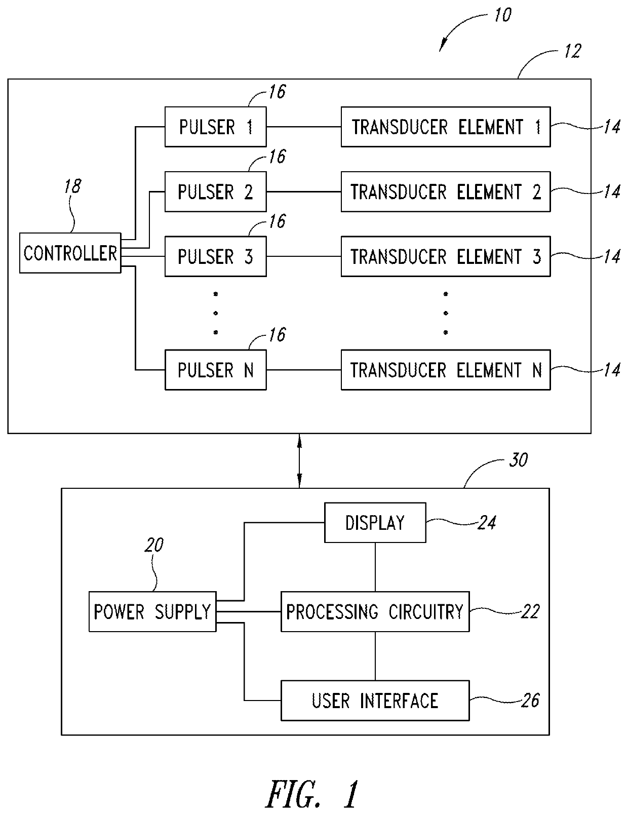
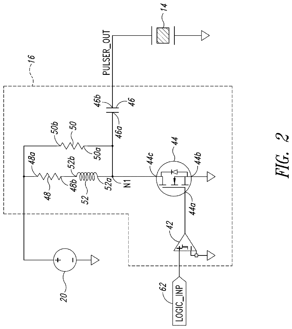
[0019]A handheld ultrasound probe may include an array of transducer elements and an array of pulse generators located within the probe. Each of the transducer elements is coupled to a respective pulse generator, which generates transmit pulses for driving the associated transducer element. The pulse generators (or “pulsers”) are driven by control signals provided from a controller circuit, which may be located within the probe or, alternatively, in a computer device which is operably coupled to the probe, e.g., via a cable. Each pulser may include a GaN FET switching element that is controlled (e.g., turned on and off) based on the control signals, and which causes a resonant portion of the pulser to resonate. By turning off the GaN FET switching element, while the pulser is resonating, a transmit pulse is generated and provided to the associated transducer element, which accordingly transmits an ultrasound signal based on the transmit pulse.

[0020]FIG. 1 is a block diagram illustra...


PUM


Abstract

Circuits, devices and methods generating an ultrasound pulse are provided herein. An ultrasound probe includes an array of transducer elements configured to transmit an ultrasound signal toward a target structure in a region of interest, and an array of pulse generators for driving a respective transducer element. Each of the pulse generators are coupled to a respective transducer element and include a driver circuit configured to receive a control signal and to output a driving signal, a switching element coupled to the driver circuit, and a resonant circuit coupled to the switching element and the respective transducer element, wherein the resonant circuit is configured to provide a transmit pulse to the respective transducer element based on the driving signal. The switching element may comprise a gallium nitride field effect transistor (GaN FET).

Description

BACKGROUNDTechnical Field[0001]The present application pertains to ultrasound systems, and more particularly to ultrasound probes including pulser circuits for generating and providing a transmit pulse to a respective transducer element.Description of the Related Art[0002]Ultrasound imaging is useful as an imaging modality in a number of environments. For example, in the field of healthcare, internal structures of a patient's body may be imaged before, during or after a therapeutic intervention. A healthcare professional may hold a portable ultrasound probe, or transducer, in proximity to the patient and move the transducer as appropriate to visualize one or more target structures in a region of interest in the patient. A transducer may be placed on the surface of the body or, in some procedures, a transducer is inserted inside the patient's body. The healthcare professional coordinates the movement of the transducer so as to obtain a desired representation on a screen, such as a tw...

Claims


Application Information

Patent Timeline
Patent Type & Authority Patents(United States)
IPC IPC(8): B06B1/06B06B1/02A61B8/00
CPCB06B1/0622A61B8/54B06B1/0215A61B8/4444A61B8/4488A61B8/4494
Inventor BROAD, RONALD W.
Owner ECHONOUS INC
Why Eureka
Try Eureka