Skid steer cutting attachment

a cutting attachment and skid steer technology, applied in the field of rotary cutters, can solve the problems of putting the operator in danger, blocking vision, and virtually impossible for the operator to effectively cut a raised surface such as concrete pipes, or a vertical surface such as walls

Active Publication Date: 2019-09-10
HEPHNER MATTHEW J +1
View PDF13 Cites 0 Cited by
  • Summary
  • Abstract
  • Description
  • Claims
  • Application Information

AI Technical Summary

Benefits of technology

[0012]In one embodiment, the house is configured to attach to the front of a skid steer such that the house rests on the ground. The arm couples the blade to the house. The arm is coupled to the cylinder. The cylinder is double actuating and configured to raise and lower the arm. The cylinder controlling the arm and the motor powering the blade operate independently of one another. In some embodiments, the cylinder controlling the arm and the motor powering the blade are powered by the same hydraulic circuit, which originates from the skid steer. The hydraulic circuit includes a flow regulator that limits the speed that the cylinder lowers the arm. The hydraulic circuit includes a release valve that reduces the downward maximum force that the cylinder is capable of exerting on the arm.
[0014]In some embodiments, the downward force of the weight of the house and its coupling to the skid steer overcomes any torque on the arm caused by the spinning blade contacting an uncuttable material. Thus, the house rests on the ground even when the blade meets resistance or binds while cutting, and thus the cut line maintains a uniform depth.
[0016]The house, guard and arm are collectively interposed between the front of the skid steer and the ground contact area of the blade. Thus, the operator of the skid steer is protected from flying debris created when the blade is cutting into the ground. In some embodiments, at least a portion of the guard is inside the channel when the blade is in contact with the ground.
[0019]The guard is capable of being rotated such that it is interposed between the front of the skid steer and the surface area being cut by the blade. Thus, the guard protects the skid steer operator from flying debris caused by the blade cutting, regardless of whether the blade is cutting horizontally (e.g., along the ground), vertically (e.g., along a wall), or some combination thereof (e.g., a raised concrete pipe).

Problems solved by technology

The resulting water, debris, and mud often spatters across the front of the skid steer, blocking vision and putting the operator in danger.
The hazard from debris also makes it virtually impossible for an operator to effectively cut a raised surface such as a concrete pipe, or a vertical surface such as a wall.
The Hilsgen and Fanslow skid steer attachments may be appropriate for cutting pavement under certain circumstances but do not fully address many of the collateral concerns related to cutting hard surfaces.
For example, Hilsgen does not cut a line of uniform depth if there is an uneven cutting surface between the skid steer and the front of the boom.
Another limitation of both Fanslow and Hilsgen is that their devices have limited ability to cut a vertical structure or an irregular structure such as a pipe.
Another limitation of both Fanslow and Hilsgen is that their devices offer no safe method for the user to climb into the front entrance of a skid steer.

Method used


Image

  • Skid steer cutting attachment
  • Skid steer cutting attachment
  • Skid steer cutting attachment

Examples


Embodiment Construction

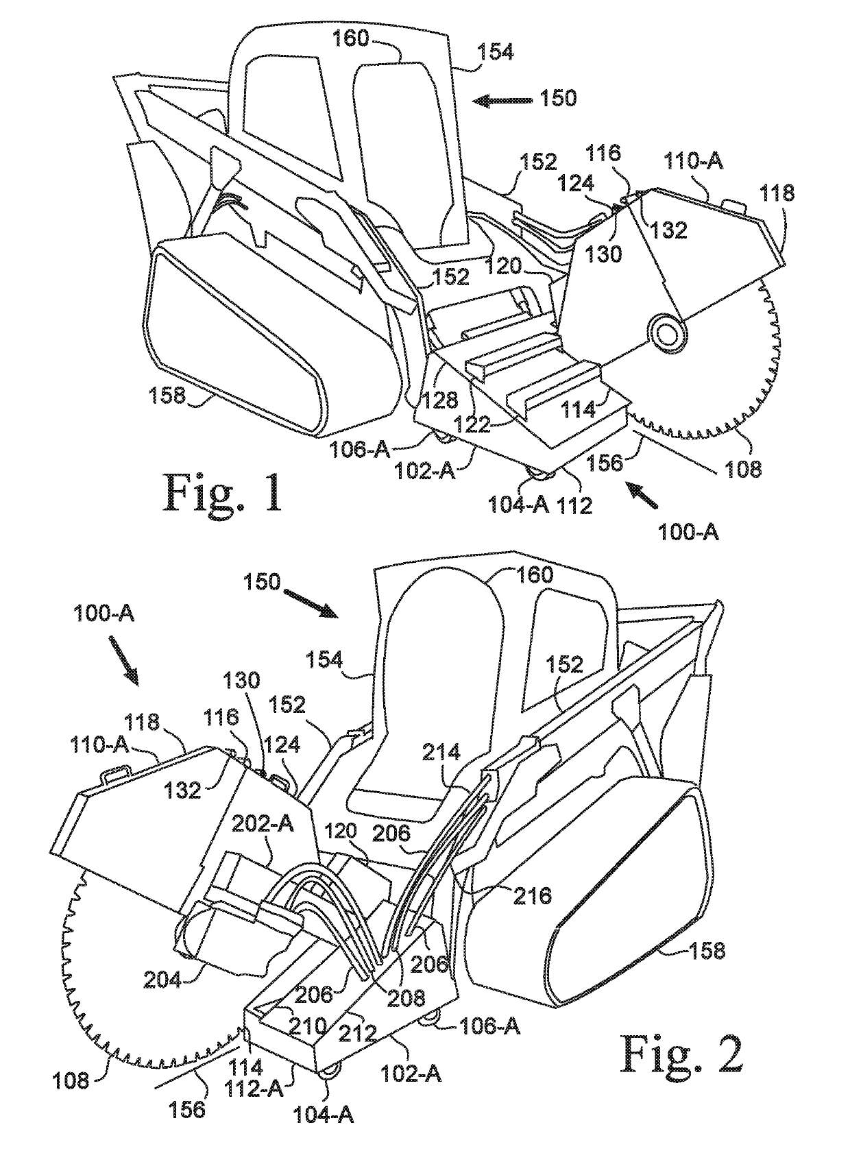
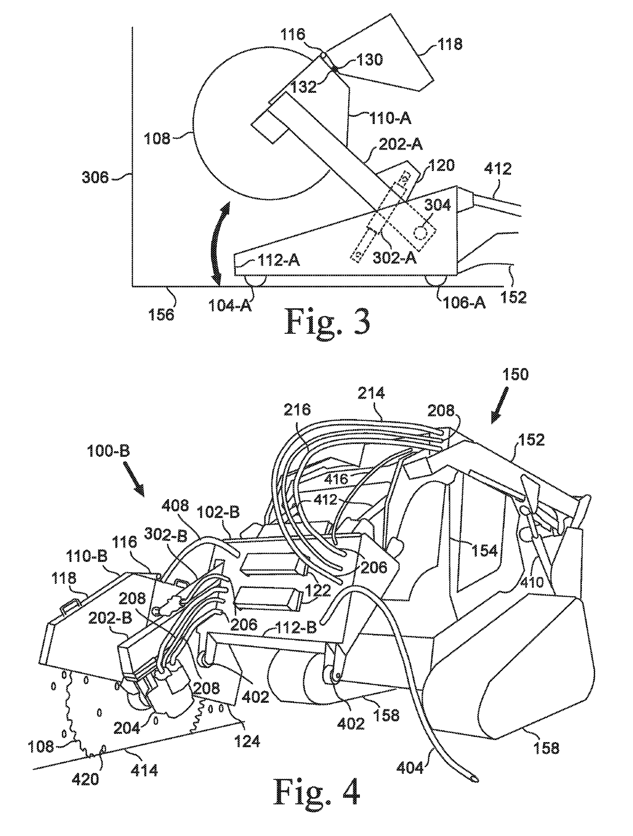
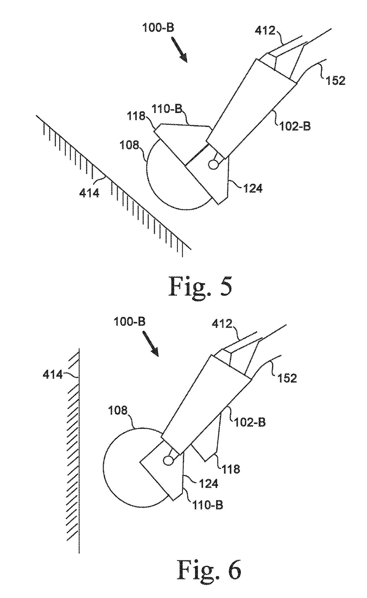
[0031]Skid steer attachment for cutting is disclosed. The skid steer attachment is generally indicated as 100, with particular embodiments and variations shown in the figures and described below having an alphabetic suffix, for example, 100-A or 100-B.

[0032]Various components are illustrated both generically and specifically in the figures and in the following description. For example, the houses 102-A, 102-B are discussed individually and separately to ensure clarity when describing the configuration of each skid steer attachment 100-A, 100-B. The house 102, when referred to collectively, is referenced without the alphanumeric suffix.

[0033]FIGS. 1 and 2 illustrate an attachment 100-A mounted on a skid steer 150. The skid steer 150 is a rigid-frame, engine-powered mobile machine with lift arms 152 suitable for attaching a wide variety of tools and attachments. The skid steer 150 often has one or more hydraulic circuits 206, which include a pressure line 214 and return line 216, that...


PUM

PropertyMeasurementUnit
pressureaaaaaaaaaa
widthaaaaaaaaaa
hydraulic pressureaaaaaaaaaa

Abstract

Cutting apparatus attachable to a skid steer. The apparatus includes a house attached to a skid steer. The house is attached to an arm, which is attached to a motor that drives a blade. A single hydraulic circuit originating from the skid steer powers both the motor and a cylinder that is capable of pivoting the arm or rotating a guard that partially surrounds the blade. The user is able to operate the motor and cylinder independently of one another. The cutting apparatus is capable of cutting a straight line on horizontal, raised, and vertical surfaces.

Description

CROSS-REFERENCE TO RELATED APPLICATIONS[0001]This application claims the benefit for Provisional Application No. 62 / 439,087, filed Dec. 26, 2016.STATEMENT REGARDING FEDERALLY SPONSORED RESEARCH OR DEVELOPMENT[0002]Not Applicable.BACKGROUND[0003]1. Field of Invention[0004]This invention pertains to rotary cutters. More particularly, this invention pertains to hydraulically-powered concrete cutters that attach to skid steers.[0005]2. Description of the Related Art[0006]Hard materials, such as concrete pavement, asphalt, wood, aluminum, and other metals, are often cut with large, hydraulically-powered blades that are attached to skid steers.[0007]During the cutting process water is constantly applied to the blade to prevent overheating, control dust, and assist in clearing out the cutting area. The resulting water, debris, and mud often spatters across the front of the skid steer, blocking vision and putting the operator in danger. The hazard from debris also makes it virtually impossi...

Claims


Application Information

Patent Timeline
Patent Type & Authority Patents(United States)
IPC IPC(8): E01C23/09B28D1/04B23D47/02B23D45/02B28D7/02B23D59/02B23D47/10B23D47/12
CPCB23D47/02B23D45/028B23D47/10B28D1/045B23D47/12E01C23/09B28D1/042B23D59/025B28D7/02
Inventor HEPHNER, MATTHEW J.HEPHNER, MATTHEW C.
Owner HEPHNER MATTHEW J
Why Eureka
Try Eureka